
Device for driving a vehicle wheel

a technology for driving wheels and vehicles, applied in mechanical equipment, belts/chains/gears, brake systems, etc., can solve the problems of screw wear, fatigue, and screw wear,

Active Publication Date: 2006-05-16
VOLVO CONSTR EQUIP HLDG SWEDEN AB
View PDF18 Cites 25 Cited by
  • Summary
  • Abstract
  • Description
  • Claims
  • Application Information

AI Technical Summary

Benefits of technology

"The present invention is a device for driving a wheel of a vehicle, which includes a hub for carrying the wheel in a rotationally fixed manner, a planetary gear connected between the driving axle and the hub, and an arrangement for fixing the hub and the planet carrier in the intended position relative to one another in the axial direction. The device is particularly useful in work vehicles such as wheel loaders, dumper vehicles, and trucks. The use of a planetary gear at each driving wheel reduces the rotational speed from the driving axle to the hub and increases torque from the driving axle to the hub. The hub and the planet carrier have holes that form a continuous opening through them, and an elongate element is fixed in the continuous opening to fix the hub and the planet carrier relative to each other in the axial direction. This construction strengthens the wheel assembly with regard to fatigue resistance. The elongate element is not subjected to varying loads when the hub rotates. The fixing arrangement also includes a portion with at least in part a greater extent in the radial direction than the holes in the hub and the planet carrier, which forms a counterstay and interacts with the hub to reduce wear and improve strength. The invention also avoids extra machining operations and reduces spline wear."

Problems solved by technology

When the hub rotates, these screws are subjected to a relatively great varying load and tend to suffer fatigue and to break off after a period of operation.

Method used


Image

  • Device for driving a vehicle wheel
  • Device for driving a vehicle wheel
  • Device for driving a vehicle wheel

Examples


Embodiment Construction

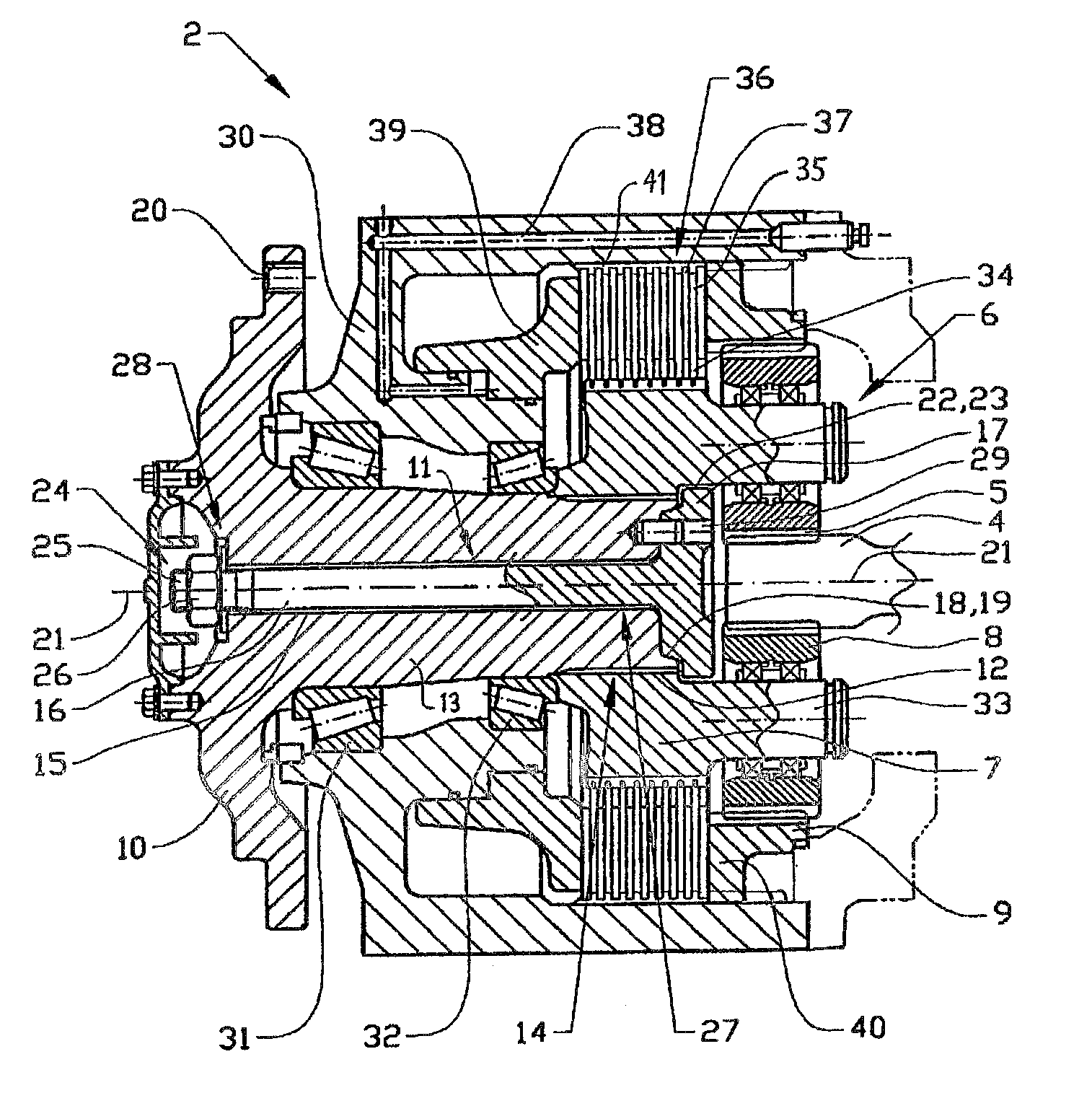
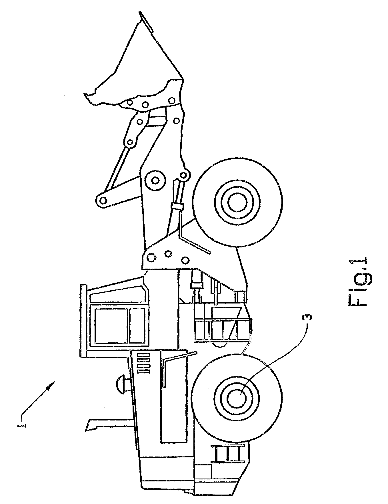
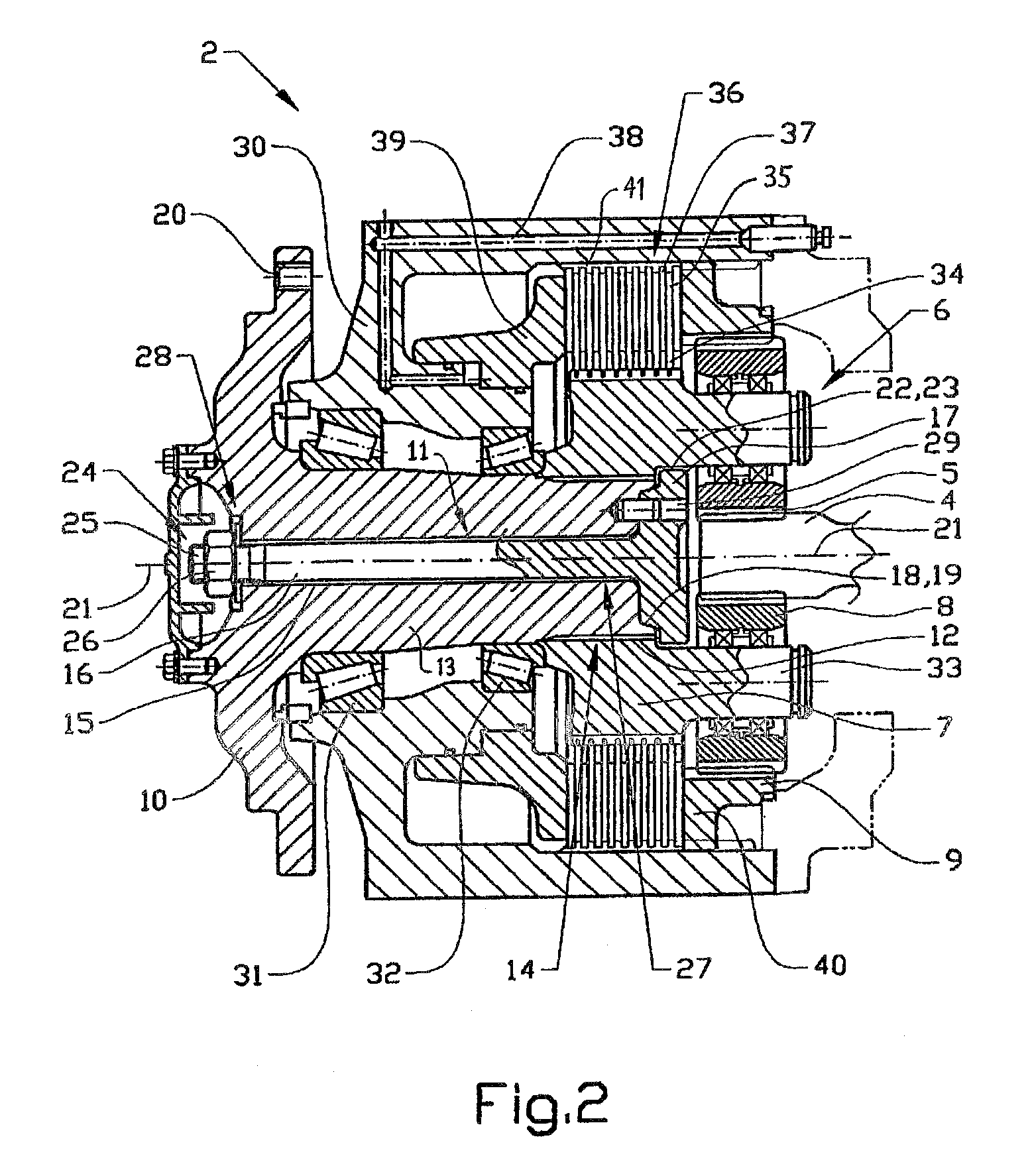
[0015]FIG. 1 shows a wheel loader 1 in a side view. Reference is also made to FIGS. 2 and 3 below. The present invention relates to a device 2 for driving a wheel 3 of the wheel loader. The wheel loader has an engine in the form of a diesel engine (not shown) which drives the wheels 3 via a transmission. To be precise, the engine drives, via a central gear in an axle case of the vehicle, a driving axle 4 which is coupled to the driving device 2 at the respective driving wheel.

[0016]To be precise, the driving axle 4 is connected in a rotationally fixed manner to a sun gear 5 which forms part of a planetary gear 6. The planetary gear 6 also comprises a planet carrier 7, at least one planet wheel 8 which is mounted on the planet carrier 7 and arranged in engagement with the sun gear 5, and a stationary ring gear 9 with internal teeth for engagement with the external teeth of the planet wheel.

[0017]The planet carrier 7 is connected in a rotationally fixed manner to a hub 10, on which th...


PUM


Abstract

The invention relates to a device for driving a wheel of a vehicle. The device includes a hub for carrying the wheel in a rotationally fixed manner, a planetary gear connected between a driving axle and the hub, which planetary gear includes a planet carrier which is connected in a rotationally fixed manner to the hub, and an arrangement for fixing the hub and the planet carrier in the intended position relative to one another in the axial direction. Both the hub and the planet carrier include a hole which extends in the axial direction. At least one of the holes forms at least a part of a continuous opening through the hub and the planet carrier in the axial direction. The fixing arrangement comprises an elongate element arranged in the continuous opening and an arrangement for fixing the hub and the planet carrier relative to one another in the axial direction via the elongate element.

Description

BACKGROUND AND SUMMARY[0001]The present application is a continuation of International Application PCT / SE2004 / 000269, filed Feb. 26, 2004, which claims priority to Swedish Application No. 0300594-9, filed Mar. 5, 2003.[0002]The present invention relates to a device for driving a wheel of a vehicle, which device comprises a hub for carrying a wheel in a rotationally fixed manner, a planetary gear connected between a driving axle and the hub, which planetary gear comprises a planet carrier which is connected in a rotationally fixed manner to the hub, and an arrangement for fixing the hub and the planet carrier in the intended position relative to one another in the axial direction. In particular, the device is intended to be applied in a work vehicle, such as a wheel loader, dumper or the like. However, the invention could also be utilized in other heavy duty vehicles, such as trucks and buses.[0003]By virtue of arranging a planetary gear at each driving wheel in this way, a reduction...

Claims


Application Information

Patent Timeline
Patent Type & Authority Patents(United States)
IPC IPC(8): F16H57/08B60K17/00B60K17/04B60T1/06F16D65/14
CPCB60K17/046B60T1/062F16D65/186F16D2121/02B60Y2200/415
Inventor ANDERSSON, THOMASLARSSON, LARSAKERBLOM, MATS
Owner VOLVO CONSTR EQUIP HLDG SWEDEN AB
Learn More