Position determination based on phase difference

a phase difference and position technology, applied in the field of position determination, can solve the problem that applications are usually limited to remote identification applications

Active Publication Date: 2006-05-16
VALTRUS INNOVATIONS LTD +1
View PDF12 Cites 70 Cited by
  • Summary
  • Abstract
  • Description
  • Claims
  • Application Information

AI Technical Summary

Problems solved by technology

However, these applications are usually ...

Method used


Image

  • Position determination based on phase difference
  • Position determination based on phase difference
  • Position determination based on phase difference

Examples


Embodiment Construction

[0019]In the following detailed description, numerous specific details are set forth in order to provide a thorough understanding of the present invention. However, it will be apparent to one of ordinary skill in the art that these specific details need not be used to practice the present invention. In other instances, well-known structures, interfaces, and processes have not been shown in detail in order not to unnecessarily obscure the present invention.

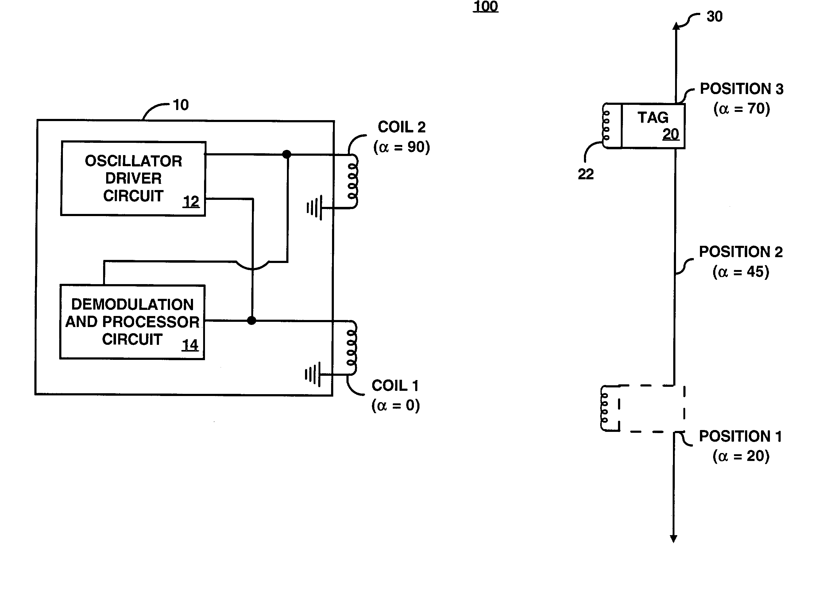
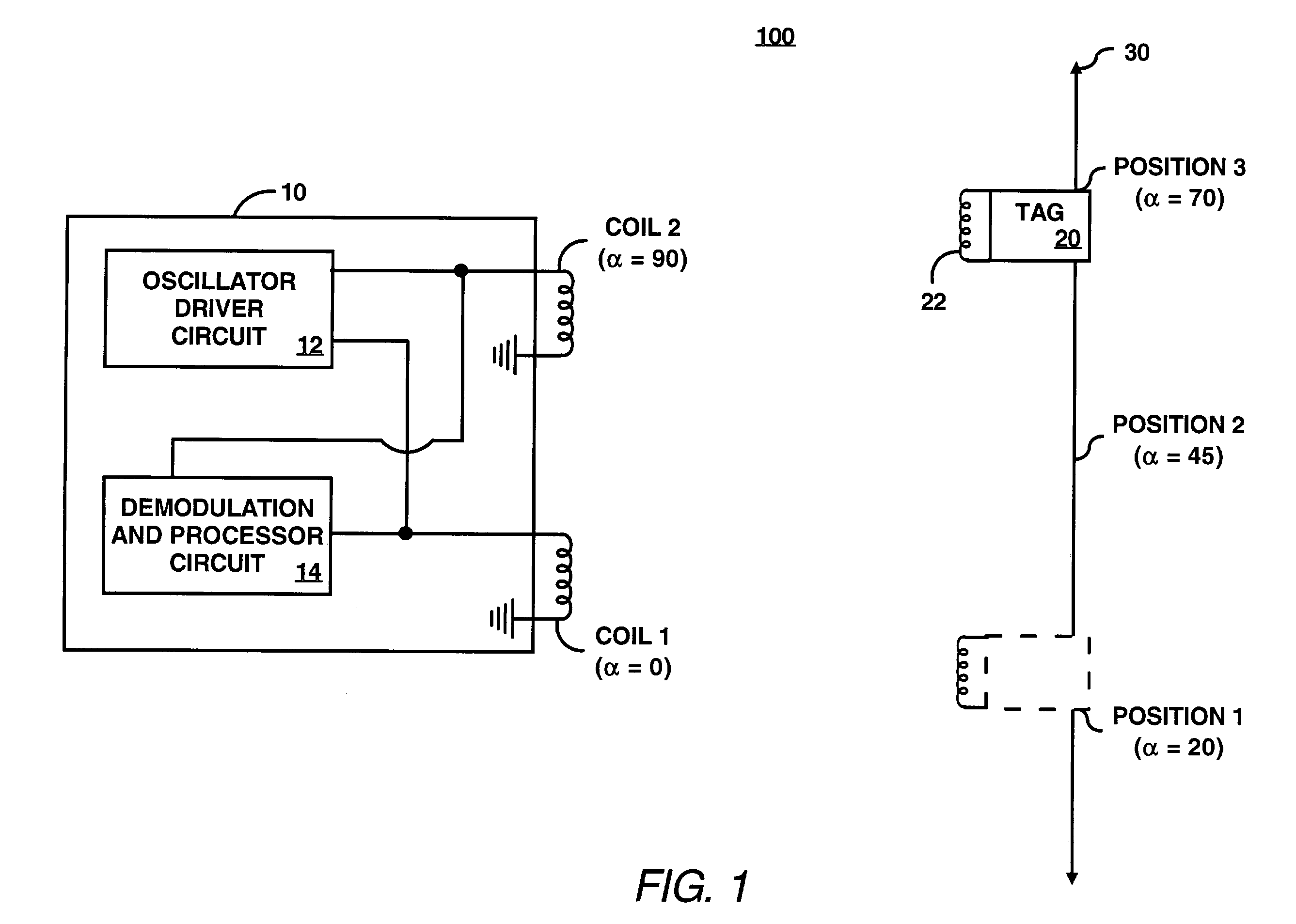
[0020]FIG. 1 illustrates a reader 10 (also known as an interrogator) and a tag 20 in a position detection system 100, according to an embodiment of the invention. The reader 10 generates a magnetic field for sensing a tag (e.g., the tag 20). The magnetic field induces an energizing signal (e.g., a current induced in a coil 22 in the tag 20) for powering the tag 20. When powered, the tag 20 modulates a signal on the magnetic field, which is used by the reader 10 to determine a position of the tag 20. The position of the tag 20 may b...


PUM


Abstract

A method for determining position of a device includes generating at least two, time-varying, magnetic fields using inductive elements, wherein the fields have differing phases. The method further includes detecting a signal modulated on top of the fields, wherein the signal is generated from the device, and determining a position of the device based on a phase difference of the signal from the device and a reference signal.

Description

FIELD OF THE INVENTION[0001]The invention pertains to position determination. More particularly, this invention relates to determining position based on a phase difference.BACKGROUND OF THE INVENTION[0002]Various systems use transponders to identify objects from a distance by associating a transponder with the object. The transponders, also known as radio frequency identification (RFID) tags, are typically programmed with unique identification codes that identify the object. FIG. 5 illustrates a conventional tag and reader system. A reader 510 may include an inductive element 512 generating a magnetic field that energizes a tag 520. The tag 520 may include an inductive element 522 and a load 524. When the tag 520 is in proximity of the reader 510, the magnetic field generated by the reader 510 energizes the tag 520 by inducing a voltage across the inductive element 522.[0003]The tag 520 may transmit limited information back to the reader 510, such as an identification code. For exam...

Claims


Application Information

Patent Timeline
IPC IPC(8): G01B7/14G01B7/30H01F5/00G01D5/48H04B5/00
CPCG01D21/00H04B5/0056H04B5/0087H04B5/0062
Inventor LYON, GEOFF M.PRADHAN, SALILPATEL, CHANDRAKANT
Owner VALTRUS INNOVATIONS LTD
Why Eureka
Try Eureka