Position sensor
- Summary
- Abstract
- Description
- Claims
- Application Information
AI Technical Summary
Benefits of technology
Problems solved by technology
Method used
Image

Examples
first embodiment
(First Embodiment)
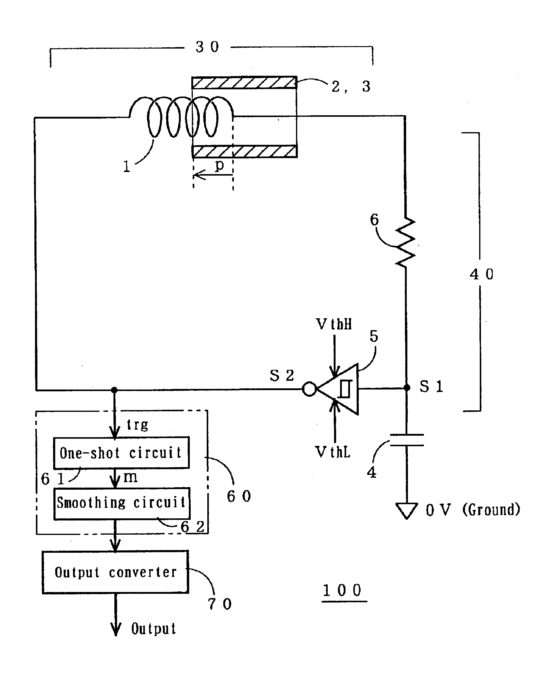
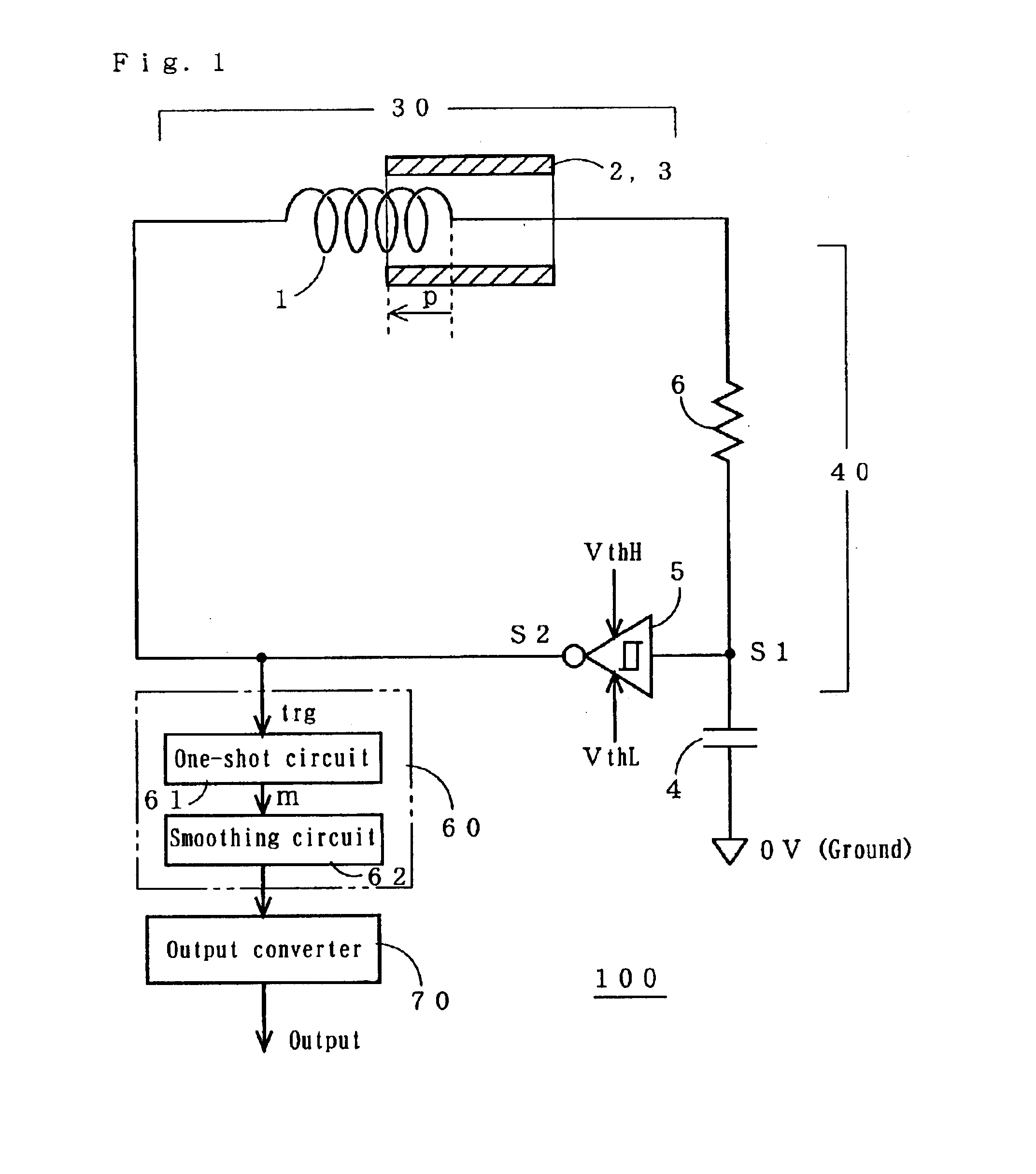
[0068]FIG. 1 is a schematic view of a position sensor 100 showing a first embodiment of the present intention.
[0069]The position sensor 100 comprises a displacement detector 30, a pulse output module 40, a voltage converter 60, and an output converter 70.
[0070]The displacement detector 30 comprises a coil 1 and an electric conductor 2 or a magnetic member 3.
[0071]The electric conductor 2 or magnetic member 3 is located relative to the coil 1 so that its overlapping length p with the coil 1 is varied depending on a positional displacement of the object to be examined.
[0072]The coil 1 may be a four-layer roll of 0.071-mm enamel coated copper wire which is 2.3 mm in inner diameter and 22 m in length and has 1240 turns. The coil 1 may be accommodated in a stainless steel protective tube which is 3 mm in inner diameter and 3.8 mm in outer diameter.
[0073]The electric conductor 2 or magnetic member 3 may be made of an aluminum tube which is 4.5 mm in inner diameter and 6....
second embodiment
(Second Embodiment)
[0111]A second embodiment of the present invention is arranged to produce an output voltage which is proportional to the displacement. As described, the output voltage in the first embodiment is inverse proportional to the displacement.
[0112]FIG. 6 is a schematic view of a position sensor 200a showing the second embodiment.
[0113]The position sensor 200a comprises a displacement detector 30, a pulse output module 40, a timing circuit 50a, a voltage converter 60, and an output converter 70.
[0114]The displacement detector 30 comprises a coil 1 and an electric conductor 2 or magnetic member 3.
[0115]The electric conductor 2 or magnetic member 3 is located relative to the coil 1 so that its overlapping length p with the coil 1 is varied depending on a positional displacement of the object to be examined.
[0116]The coil 1 may be a four-layer roll of 0.071-mm enamel coated copper wire which is 2.3 mm in inner diameter and 22 mm in length and has 1240 turns. The coil 1 may ...
third embodiment
(Third Embodiment)
[0159]A third embodiment of the present invention is arranged to produce a desired level of output voltage even when the time constant determined by a combination of the coil 1, the resistor 6, and the capacitor 4 is much smaller than the period T of the clock signal CK. This may occur when the inductance of the coil1 becomes low due to dimensional limitations. In this case, the output voltage may be low in the second embodiment.
[0160]FIG. 11 is a schematic view of a position sensor 200b showing the third embodiment.
[0161]The position sensor 200b is substantially identical in the arrangement to the position sensor 200a of the second embodiment, excluding a timing circuit 50b.
[0162]The timing circuit 50b comprises an oscillator 51, a flip-flop 52, an AND circuit 53, a buffer 54, and a counter circuit 56.
[0163]The buffer 54 in the timing circuit 50b is connected at its output port to the other end of the series circuit composed by the coil 1 and the resistor 6.
[0164...
PUM
 Abstract
Description
Claims
Application Information
 - R&D
- Intellectual Property
- Life Sciences
- Materials
- Tech Scout
- Unparalleled Data Quality
- Higher Quality Content
- 60% Fewer Hallucinations
Browse by: Latest US Patents, China's latest patents, Technical Efficacy Thesaurus, Application Domain, Technology Topic, Popular Technical Reports.
© 2025 PatSnap. All rights reserved.Legal|Privacy policy|Modern Slavery Act Transparency Statement|Sitemap|About US| Contact US: help@patsnap.com