Communication terminal

a technology of communication terminals and terminals, applied in the field of communication terminals, can solve the problems of antennas being inconveniently hooked on the edge of the pocket, affecting the reception efficiency of electromagnetic waves, so as to reduce the quantity of electromagnetic waves absorbed by the human body

Inactive Publication Date: 2006-05-16
PANASONIC CORP
View PDF20 Cites 15 Cited by
  • Summary
  • Abstract
  • Description
  • Claims
  • Application Information

AI Technical Summary

Benefits of technology

[0010]According to this structure, in the opening and closing type communication terminal having a flexible base provided in the hinge part, even when the flexible conductor is disposed near the antenna, the flexible base is separated from the feeding part of the antenna. Thus, the influence of the flexible conductor to an antenna performance can be eliminated and the deterioration of the gain of the antenna can be suppressed even under any of opening and closing states.
[0012]According to this structure, when the two casing members are opened, the high frequency electric current of an opposite phase supplied from the one casing member to the other casing member can be eliminated. Further, when the two casings are closed, the high frequency electric current supplied to the other casing member is allowed to have the same phase as that of the high frequency electric current supplied to the one casing member.
[0014]According to this structure, the break and disconnection of the flexible base due to the opening and closing operations of the casing members can be avoided. Accordingly, the life of the flexible base can be lengthened. Further, the curvature of the winding part is changed in accordance with the opening and closing operations of the two casing members so that the flexible conductor comes near to the antenna. Even at this time, since the flexible conductor is disposed in a part opposite to the feeding part of the antenna to which the high frequency electric current is concentrated, the deterioration of characteristics of a voltage-standing-wave ratio (VSWR) as one of various characteristics of the antenna can be avoided and a stable antenna gain can be obtained.
[0018]According to this structure, even when the antenna does not protrudes from the casing member, the deterioration of an antenna performance can be avoided and adequate radiation characteristics can be obtained.
[0020]According to this structure, one antenna has a plurality of resonance points (resonance frequency) and the change of an antenna gain in a low frequency band can be prevented in any of opening and closing states.
[0024]According to this structure, when a user holds the communication terminal by hand, the antenna can be hardly covered with the hand and the antenna can be separated from the head part of the human body. Thus, a quantity of electromagnetic wave absorbed by the human body can be reduced.

Problems solved by technology

Accordingly, when a casing closing state is changed to a casing opening state, radiation efficiency may be probably undesirably deteriorated.
In the protruding antenna as described above, when a user takes out the communication terminal accommodated in a pocket, the antenna is inconveniently hooked on the edge part of the pocket.
However, when various compound stresses act on the flexible base, a disconnection or a break is caused.
Accordingly, in the usual communication terminal, when the opening and closing operations of the casings are repeated, the disconnection or the break of the flexible base may be possibly caused.

Method used


Image

  • Communication terminal
  • Communication terminal
  • Communication terminal

Examples


Embodiment Construction

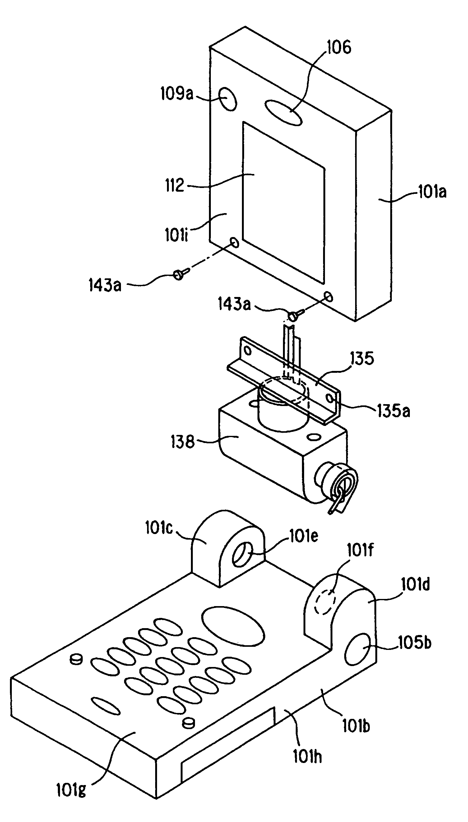
[0047]Now, embodiments of an opening and closing type or collapsible communication terminal according to the present invention will be described below by referring to the drawings. In the embodiments, the communication terminal will be described as an opening and closing type or collapsible portable telephone terminal that meets a W-CDMA (Wide band Code Division Multiple Access) system and a GSM (Global System for Mobile Communication) system. However, the communication terminal is not limited to the portable telephone terminal and may be applied to any other communication terminals that are opening and closing types.

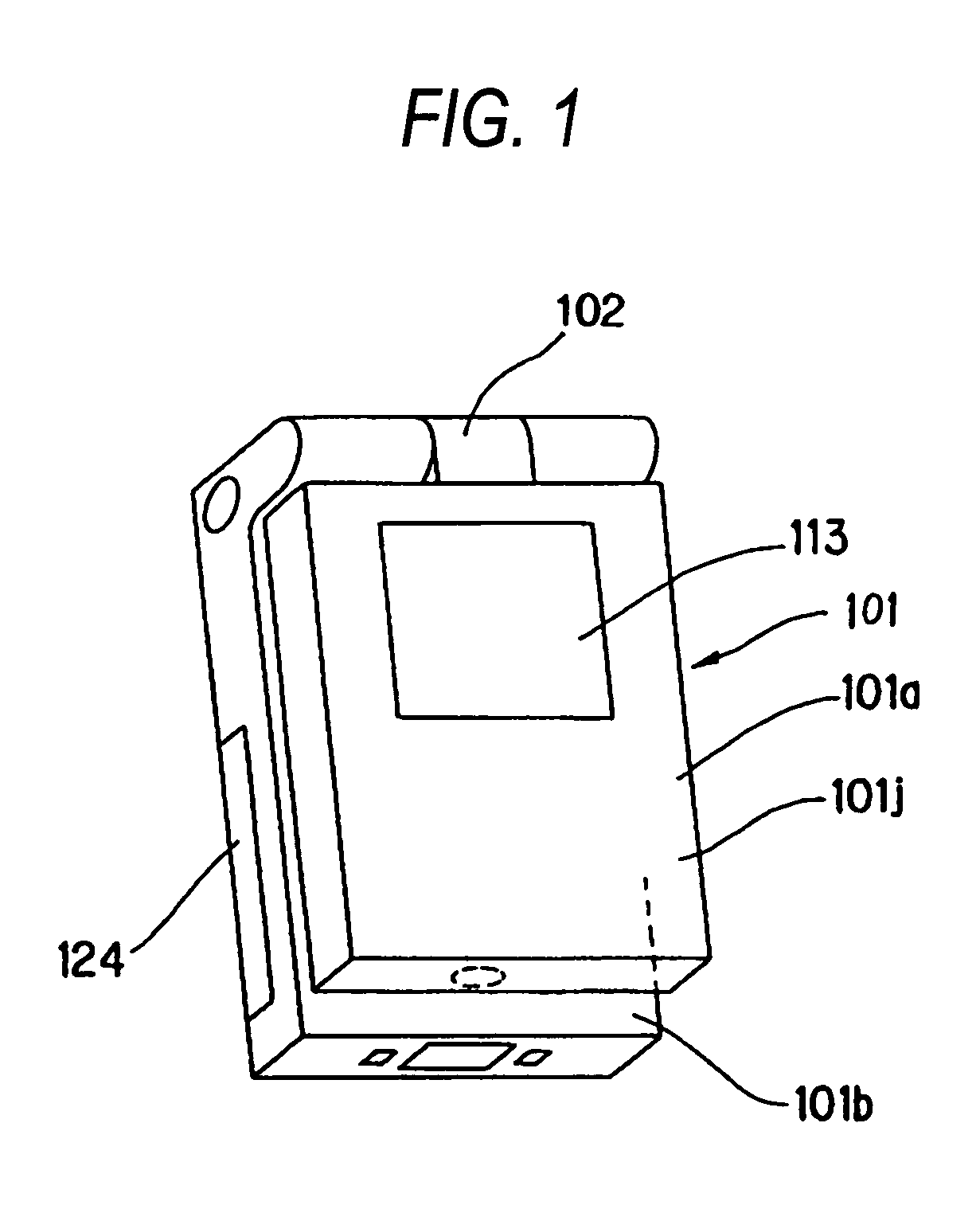
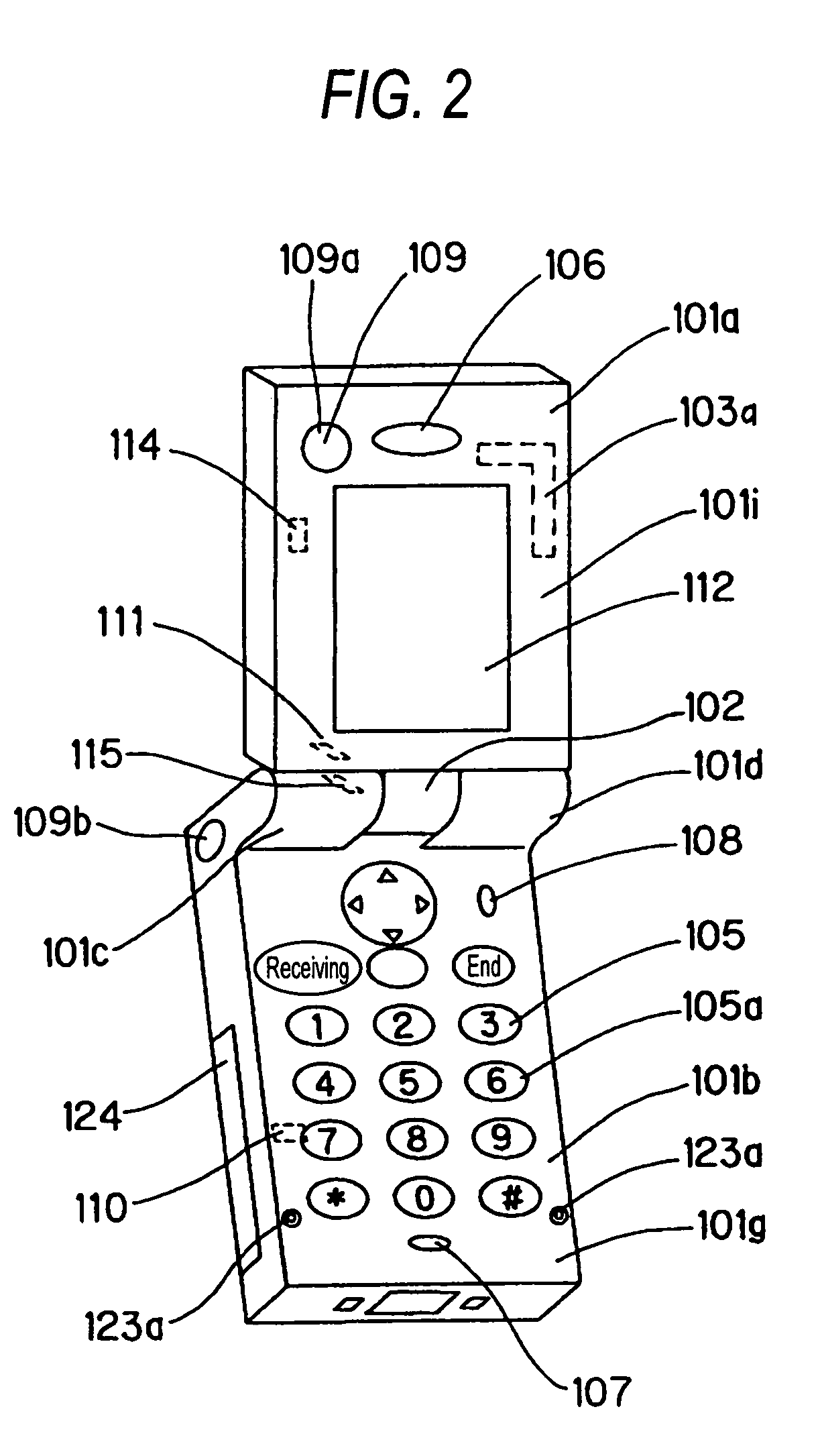
[0048]FIG. 1 is a perspective view showing the closing state of an opening and closing type or collapsible communication terminal according to one embodiment of the present invention. FIG. 2 is a perspective view showing a first opening state of the opening and closing type communication terminal according to one embodiment of the present invention. FIG. 3 is a perspect...


PUM


Abstract

It is an object of the present invention to provide a communication terminal that can suppress the deterioration of a gain of an antenna either in an opening state or in a closing state. The communication terminal includes a hinge part for connecting a first casing member (101a) to a second casing member (101b) so as to freely open and close, a second antenna (103b) provided near the hinge part in the second casing member (101b) and a flexible base for connecting together first and second printed circuit boards (116a) and (116b) respectively provided in the first and second casing members (101a) and (101b). The hinge part includes a first rotating shaft serving as an axis when the two casing members (101a) and (101b) rotate in opposed directions and a second rotating shaft serving as an axis upon rotating in a direction perpendicular to the rotating direction by the first rotating shaft. The flexible base is disposed in one end side of the first rotating shaft and a feeding part (103h) of the second antenna (103b) is disposed in the other end side of the first rotating shaft.

Description

TECHNICAL FIELD[0001]The present invention relates to a communication terminal having a freely opening and closing casing and more particularly to a casing structure of a communication terminal having an antenna for transmitting and receiving a radio signal.BACKGROUND ART[0002]As a first example of a usual freely opening and closing type communication terminal, a communication terminal is disclosed in Patent Document 1. Here, the communication terminal is described by using the drawings. FIG. 20 is a view showing the structure of the usual communication terminal and a principle of an operation of an antenna provided therein. FIG. 20(a) shows a state that a casing is closed and FIG. 20(b) shows a state that the casing is opened. In FIGS. 20(a) and 20(b), the communication terminal includes a first casing 202 connected to an antenna 201 capable of being pulled out and a second casing 203 located in the side surface of the antenna 201 upon using and made of metal or a material includin...

Claims


Application Information

Patent Timeline
Patent Type & Authority Patents(United States)
IPC IPC(8): H01Q1/24H01Q1/08H01Q1/38H01Q3/08H01Q5/10H01Q5/321H01Q9/16H01Q9/30H01Q9/32H01Q21/28H04M1/02
CPCH01Q1/084H01Q1/242H01Q1/243H01Q1/244H01Q1/245H01Q3/08H01Q5/321H01Q9/30H01Q9/32H01Q21/28H04M1/0212H04M1/0241H01Q9/16H04M1/0218
Inventor SATOH, NORIYOSHISATO, KENICHIKOMUKAI, YASUNORI
Owner PANASONIC CORP
Why Eureka
Try Eureka