Optical fiber coupling arrangement

Inactive Publication Date: 2006-05-16
COHERENT INC
View PDF20 Cites 74 Cited by
  • Summary
  • Abstract
  • Description
  • Claims
  • Application Information

AI Technical Summary

Benefits of technology

[0010]In one aspect, an apparatus in accordance with the present invention comprises an amplifier fiber having a doped core surrounded by a cladding. The core doping provides optical gain for light propagating therein when the doped core is energized by pump light absorbed in the core. An optical pumping arrangement for the amplifier fiber includes one or more transmission fibers. The optical arrangement is configured to insert pump-light from a source thereof into the amplifier fiber cladding such that the pump light propagates in the cladding. The optical arrangement is further configured to receive an unabsorbed portion of the propagated pump light from the cladding, and re-insert the unabsorbed portion of the pump-light into the cladding for re-propagation therein.
[0011]The inventive apparatus is particularly useful for pumping lengths of amplifier fiber that are too short to allow all of the pump light propagating in the cladding to be absorbed in the amplifier fib

Problems solved by technology

Extracting and re-inserting unabsorbed pump light ma

Method used


Image

  • Optical fiber coupling arrangement
  • Optical fiber coupling arrangement
  • Optical fiber coupling arrangement

Examples


Embodiment Construction

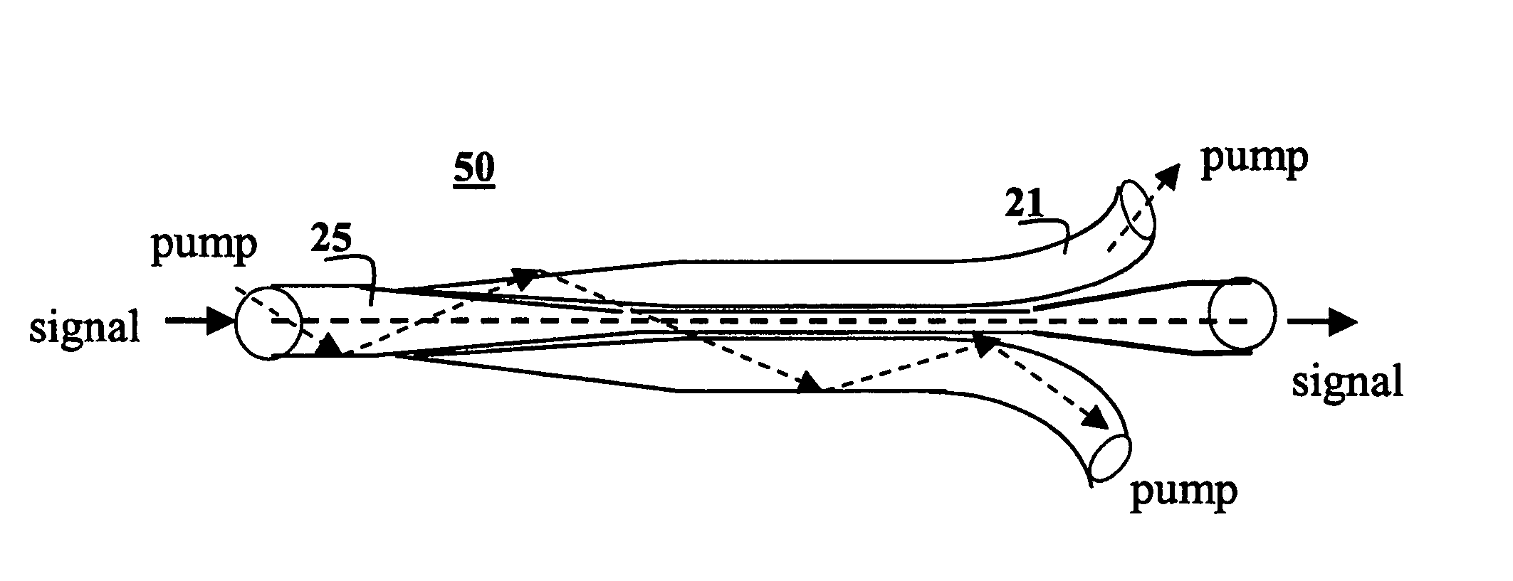
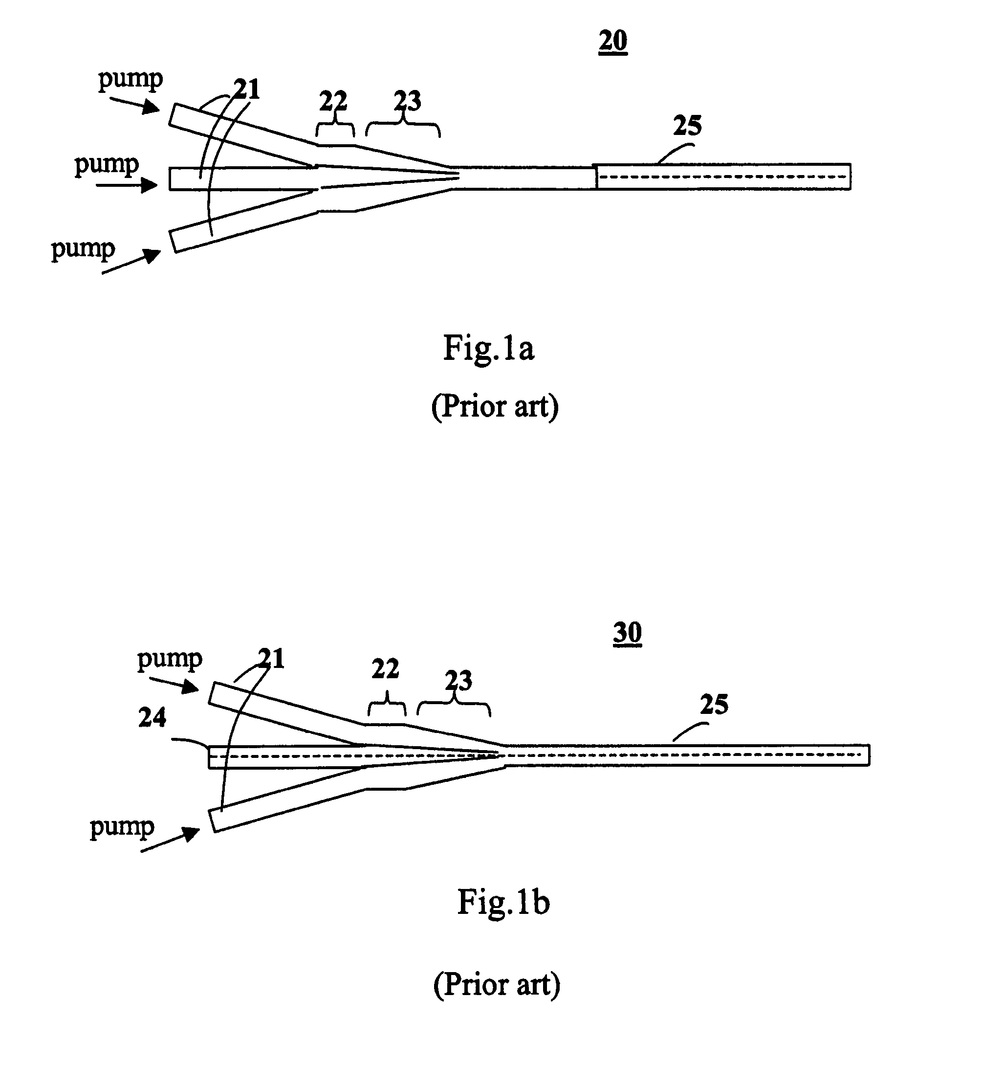
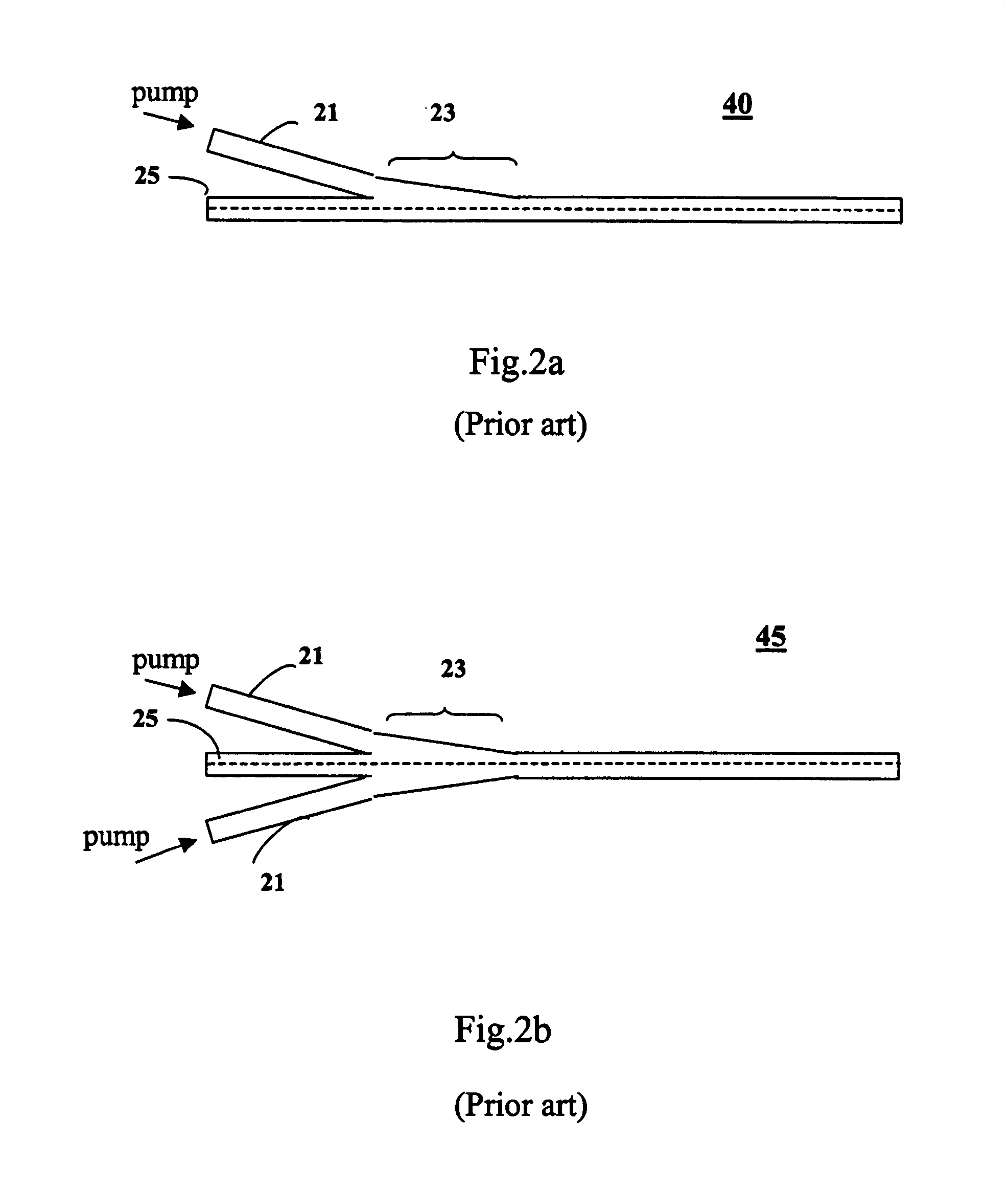
[0028]FIGS. 1a–1b illustrate the prior art arrangement based on a tapered fiber bundles for coupling light into cladding-pumped fibers. FIG. 1a illustrates an arrangement (20) comprising a plurality of individual multimode fibers (21), which converge to a bundled region (22), which extends to a tapered region (23). The bundle tapers to a minimum diameter closely approximating the diameter of the cladding-pumped fiber (25). Finally, the tapered bundle is spliced to a cladding-pump fiber. Alternatively, the tapered bundle can be first spliced to an intermediate multimode fiber, which in its turn is spliced to a cladding-pumped fiber. Any of these arrangements can be referred to as bundling the plurality of optical fibers into a single composite fiber. It is contemplated that each individual multimode fiber (21) (of which only three are shown in FIG. 1a) will couple light from an associated semiconductor emitter source. FIG. 1b shows an alternative arrangement (30) where one of the bun...


PUM


Abstract

Apparatus for optically pumping a clad amplifier fiber includes one or more transmission fibers arranged and configured to insert pump-light from a pump light source such as a diode-laser into the cladding of the amplifier fiber. The pump light propagates through the cladding and a portion of the pump light is absorbed in the doped core of the amplifier fiber. At least one of the transmission fibers is arranged to receive an unabsorbed portion of the propagated pump light from the amplifier cladding and re-insert the unabsorbed portion of the pump-light into the cladding for re-propagation through the cladding. This provides that pump light that would otherwise be wasted is circulated through the amplifier fiber for further absorption by the amplifier core.

Description

PRIORITY[0001]This application claims priority from prior provisional application Ser. No. 60 / 446,201 filed Feb. 11, 2003 the disclosure of which is incorporated herein by reference.FIELD OF THE INVENTION[0002]This invention relates to optical fibers and systems containing such optical fibers, and, in particular, to cladding-pumped waveguide and fiber lasers and amplifiers.BACKGROUND OF THE INVENTION[0003]Cladding pumped (also called double-clad) fiber lasers and amplifiers are good converters of low brightness radiation from laser diodes to a high brightness single-mode radiation. All-fiber construction and the robust monolithic design provide good stability and excellent beam quality thereby making fiber lasers a unique source for many industrial, military, scientific and medical applications.[0004]A typical cladding-pumped fiber comprises a single-mode (or a few mode) core doped with rare-earth ions and a plurality of cladding layers supporting multi-mode pumping light. The inner...

Claims


Application Information

Patent Timeline
IPC IPC(8): H04B10/12G02B6/42H01S3/00H01S3/067H01S3/094
CPCH01S3/094003H01S3/06708
Inventor STARODOUMOV, ANDREI
Owner COHERENT INC
Why Eureka
Try Eureka