
Data storage system

Inactive Publication Date: 2006-05-16
HITACHI LTD
View PDF23 Cites 31 Cited by
  • Summary
  • Abstract
  • Description
  • Claims
  • Application Information

AI Technical Summary

Benefits of technology

[0012]Further, another object of the present invention is to reduce the capacity of the entire apparatus to be smaller than those by conventional art.
[0024]In introduction of novel structure in an engagement portion between an insertion / withdrawal portion of module unit to be inserted / withdrawn and a fixed portion into which the unit is to be inserted, a comparatively low-price structure can be realized at a low cost, and further, electrical connection can be mechanically made single-handedly in a stable manner.

Problems solved by technology

Further, in a hard disk drive (HDD) in an HDD module using a magnetic disk as an information recording medium, the life is shortened at high temperatures.
H9-114553, as a particular cooling structure is arranged as the apparatus structure, the cooling means performs its function, however, the capacity of the apparatus is large due to the arrangement.
U.S. Pat. No. 5,247,427 discloses a structure where air is taken in from a front surface of an apparatus and exhausted from its rear surface, however, insertion / withdrawal of devices is not made from the rear surface.
However, there is no consideration of insertion / withdrawal of devices.
Further, the inventors consider that in the point of cooling effect and various wiring structures including arrangement of components, the apparatus structure is susceptible to further improvement.

Method used


Image

  • Data storage system
  • Data storage system
  • Data storage system

Examples


Embodiment Construction

[0046]A preferred embodiment of the present invention will now be described in detail in accordance with FIGS. 1 to 19.

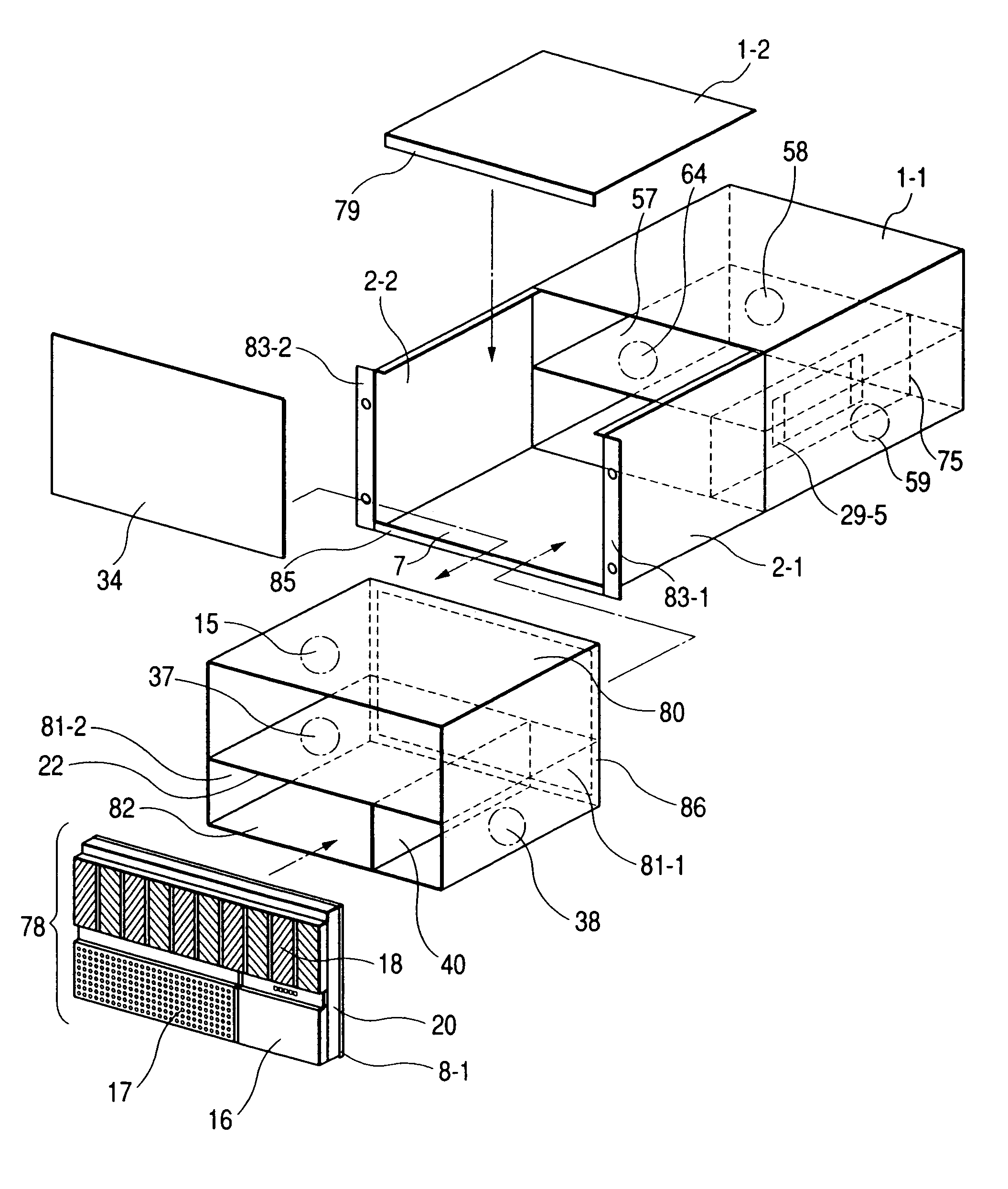
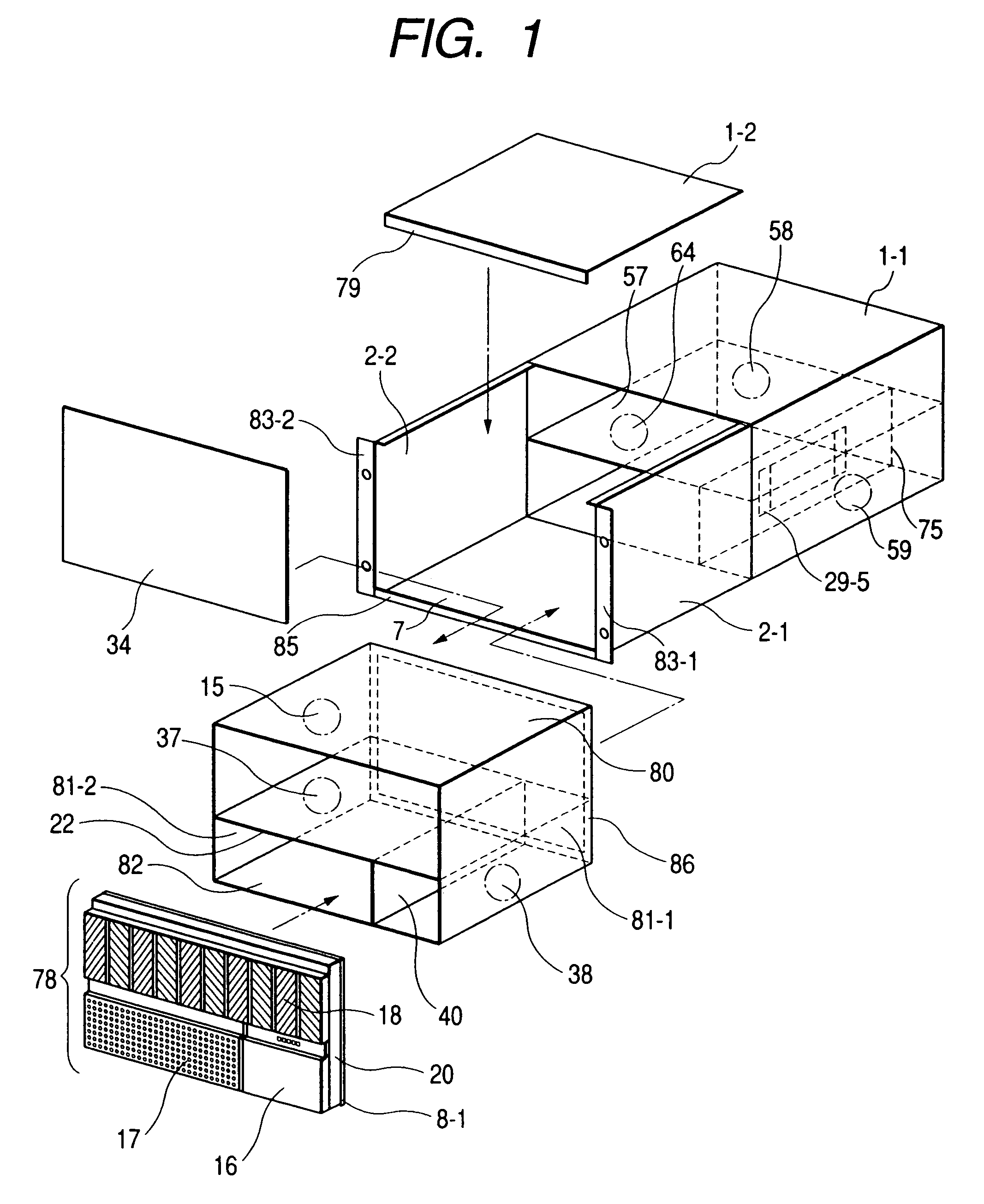
[0047]FIGS. 1 and 2 show a disk array apparatus as an example of the information storage apparatus or information storage control apparatus of the present invention. FIG. 1 is a schematic exploded perspective diagram showing the structure of the apparatus. FIG. 2 is a schematic perspective diagram viewed from a front right direction of the apparatus.

[0048]A rear upper plate 1-1 forming a rear surface upper wall, a lower plate 7, provided in a position opposite to the rear upper plate 1-1, forming a lower wall, a side plate 2-1 forming a right wall, a side plate 2-2 forming a left wall, are provided on a main body rear surface. A front surface of the apparatus has a front door provided with a cover 20 and the like having a bezel 78 including an operating cover 16, an air intake cover 17 having an air inlet, a louver 18 and an EMI gasket(1) 8-1. The air intake cover 1...


PUM


Abstract

The information storage apparatus has an internal structure and arrangement of fans in consideration of the cooling effect. The capacity of the entire apparatus can be smaller than that of a conventional apparatus and an optimum air channel can be formed so as to maintain reliability of performance, life and the like of components at high temperatures. Further, relatively speaking, a module which does not produce a large amount of heat and does not require cooling is provided in a front stage of the channel while a module including heat-producing components and a cooling fan is provided in a rear stage of the channel.

Description

[0001]This is a continuation application of U.S. Ser. No. 09 / 761,773, filed Jan. 18, 2001 now abandoned.BACKGROUND OF THE INVENTION[0002]The present invention relates to the construction, arrangement and structure of information storage apparatus and information storage control apparatus, among apparatuses constructing an information storage system, and more particularly, to cooling means for cooling internal components, transmission means for transmitting display information to a status display unit, and attachment / detachment mechanism for detachably installed modules.[0003]In information storage apparatuses or information storage control apparatuses, it is necessary to cool down the respective modules inside the apparatus to ensure reliability. Especially, in a micro processing unit (MPU) incorporated into a control module, the computation speed is reduced at high temperatures. Further, in a hard disk drive (HDD) in an HDD module using a magnetic disk as an information recording m...

Claims


Application Information

Patent Timeline
IPC IPC(8): G11B15/18G06F1/20G11B33/14H05K7/20
CPCG06F1/20H05K7/20581G11B33/142
Inventor YAMANASHI, AKIRATAKAHASHI, HIROKAZUISHIKAWA, TAKAMASATATEYAMA, KENICHI
Owner HITACHI LTD
Features
  • Generate Ideas
  • Intellectual Property
  • Life Sciences
  • Materials
  • Tech Scout
  • Unparalleled Data Quality
  • Higher Quality Content
  • 60% Fewer Hallucinations
Learn More