Interference canceller with fast phase adaptation

a phase adaptation and interference canceller technology, applied in the field of wireless communication, can solve the problem of almost inevitable interference between signals, and achieve the effect of reducing interference between transmission channels

Active Publication Date: 2006-05-16
MAXLINEAR ISRAEL LTD
View PDF33 Cites 22 Cited by
  • Summary
  • Abstract
  • Description
  • Claims
  • Application Information

AI Technical Summary

Benefits of technology

[0006]Embodiments of the present invention provide improved methods and devices for interference cancellation, which are useful particularly in cross-polarization interference cancellation. In these embodiments, a transmitter transmits first and second signals over the air on first and second transmission channels, which typically have respective, orthogonal polarizations. A receiver downconverts and digitizes the first and second signals to generate fist and second streams of input digital samples. These samples are processed by a novel XPIC device in order to generate output samples in which the interference between the transmission channels is reduced. A decision device, such as a slicer, extracts the transmitted symbols from the interference-corrected outputs of the XPIC device.
[0008]The phase correction applied by the rotator is determined adaptively by a fast process, based on the varying phase deviation between the transmission channels. The inventors have found that separating the fast phase rotation and slow filter adaptation processes in the XPIC device accords well with the actual physical processes that operate on the transmission channels themselves. By applying the phase correction in the digital domain, after filtering the individual sample streams, the control loop of the phase rotator is shortened. This configuration accelerates the convergence of the phase correction process, and therefore gives enhanced interference cancellation relative to systems known in the art.

Problems solved by technology

Despite the orthogonality of the channels, however, some interference between the signals occurs almost inevitably.

Method used


Image

  • Interference canceller with fast phase adaptation
  • Interference canceller with fast phase adaptation
  • Interference canceller with fast phase adaptation

Examples


Embodiment Construction

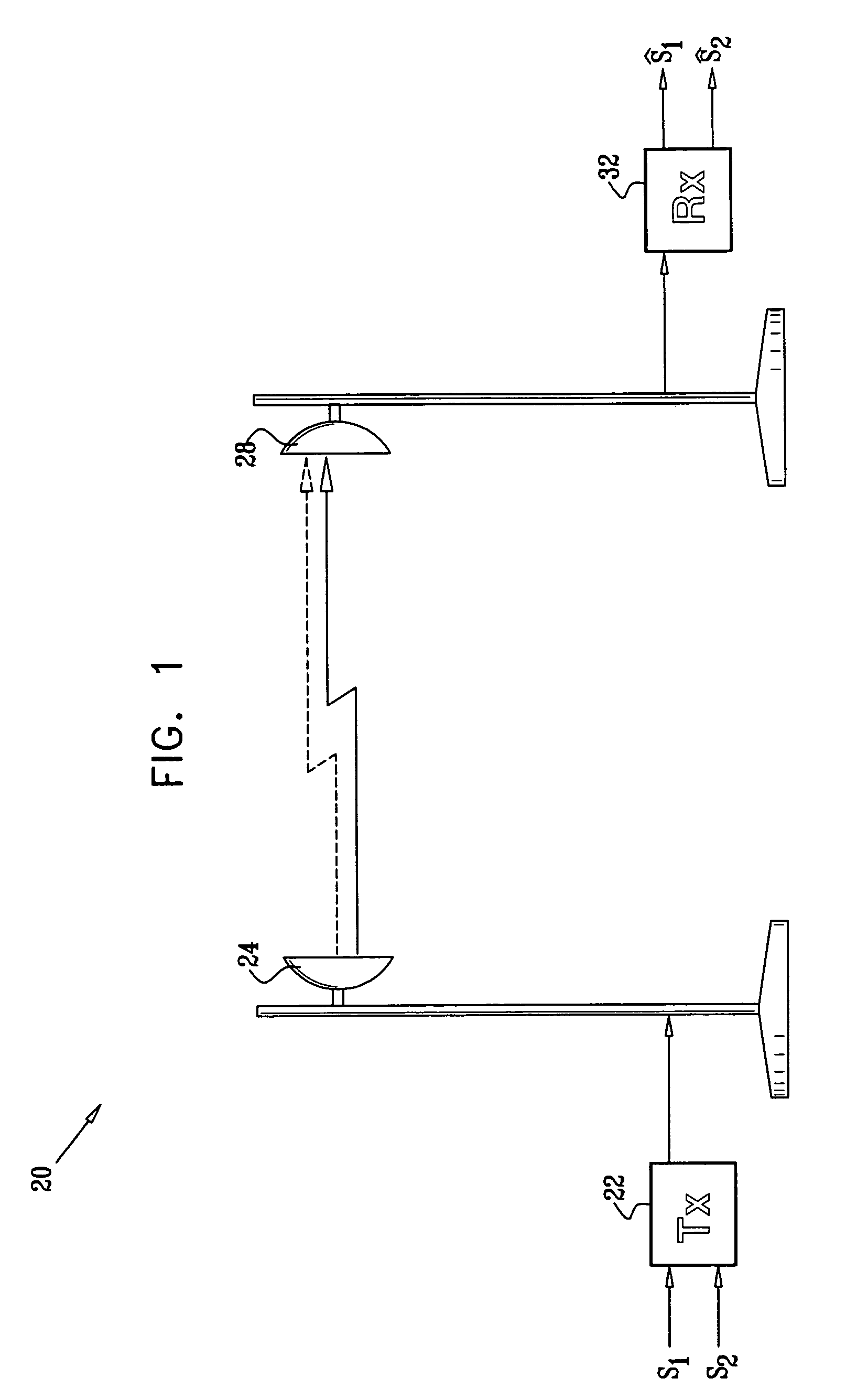
[0063]FIG. 1 is a block diagram that schematically illustrates a wireless data transmission system 20, in accordance with a preferred embodiment of the present invention. System 20 comprises a transmitter 22, which is coupled to transmit signals s1 and s2 over the air via a transmit antenna 24. Typically, s1 and s2 carry streams of digital data, which are converted to data symbols by transmitter 22 according to a suitable modulation scheme, and are then upconverted to a predetermined radio frequency (RF) range for transmission, as is known in the art. Transmitter 22 and antenna 24 are configured to transmit s1 and s2 on orthogonally-polarized transmission channels. For example, the antenna may transmit s1 with vertical polarization and s2 with horizontal polarization. Alternatively, the signals may be transmitted with clockwise and counterclockwise circular polarizations. Further alternatively, separate transmit antennas (and / or separate received antennas) may be used for the two po...


PUM


Abstract

A receiver includes an input circuit, which is coupled to at least one antenna so as to receive, process and digitize first and second signals, thus generating first and second streams of input samples. An interference cancellation circuit includes first and second processing chains, which are reaspectively coupled to filter the first and second streams of input samples using respective first and second adaptive coefficients to generate respective first and second filter outputs, at least one of the first and second processing chains being further adapted to apply a variable phase shift so as to compensate for a phase deviation between the first and second signals. An adder sums the first and second filter outputs so as to generate a third stream of output samples, which is representative of the first signal. A coefficient controller is operative to set the first and second adaptive coefficients and to separately set the variable phase shift responsively to the output samples.

Description

FIELD OF THE INVENTION[0001]The present invention relates generally to wireless communications, and specifically to methods and systems for increasing wireless link capacity by using multiple receivers.BACKGROUND OF THE INVENTION[0002]Polarization diversity can be used to provide two parallel communication channels over the same link with orthogonal polarizations, thus doubling the link capacity. Separate and independent signals are transmitted over the two channels thus defined. Despite the orthogonality of the channels, however, some interference between the signals occurs almost inevitably. In order to cancel the effects of this interference, the receiver may comprise a cross-polarization interference canceller (XPIC), which processes and combines the signals from the two receive antennas in order to recover the original, independent channel signals.[0003]A variety of XPIC circuits are known in the art. For example, U.S. Pat. No. 4,914,676, whose disclosure is incorporated herein...

Claims


Application Information

Patent Timeline
Patent Type & Authority Patents(United States)
IPC IPC(8): H04B1/10H03D1/06H04B7/08H04B7/10H04L1/00H04L25/08
CPCH04B7/10H04B7/0837
Inventor RESHEFF, GUYCHARASH, DAN
Owner MAXLINEAR ISRAEL LTD
Why Eureka
Try Eureka