Method for diagnosing the operational state of a two-step variable valve lift device

a technology of variable valve and operation state, which is applied in the direction of machines/engines, electrical control, instruments, etc., can solve the problems of inability to reliably determine whether one or more of the two-step cam profile switching mechanisms used in the internal combustion engine are in the wrong mode of operation, and the performance of the internal combustion engine is limited by fixed valve lift profiles

Active Publication Date: 2006-05-23
DELPHI TECH IP LTD
View PDF8 Cites 40 Cited by
  • Summary
  • Abstract
  • Description
  • Claims
  • Application Information

AI Technical Summary

Benefits of technology

[0008]Briefly described, the present invention is directed to a method for determining whether a two-step variable valve lift device is operating in the improper mode of operation. In particular, the method is performed in real-time in the embedded engine or powertrain controller and monitors existing engine parameters, such as instantaneous cylinder pressure or torque, using preexisting sensors. The measured engine parameters are then compared with an expected range of predetermined values to det

Problems solved by technology

Historically, the performance of an internal combustion engine has been limited by fixed valve lift profiles, i.e., fixed timing of the opening and closing of the valves relative to the angular position of the engine crankshaft and fixed lift of the valves.
Currently there are no reliable methods of reliably determining whether one or more of the two-step cam profile switching mechanisms used in an internal combustion engine are in the wrong mode of operation while the engine is cranking and running.
Both of the hands-on approaches requires that a person, such as

Method used


Image

  • Method for diagnosing the operational state of a two-step variable valve lift device
  • Method for diagnosing the operational state of a two-step variable valve lift device
  • Method for diagnosing the operational state of a two-step variable valve lift device

Examples


Embodiment Construction

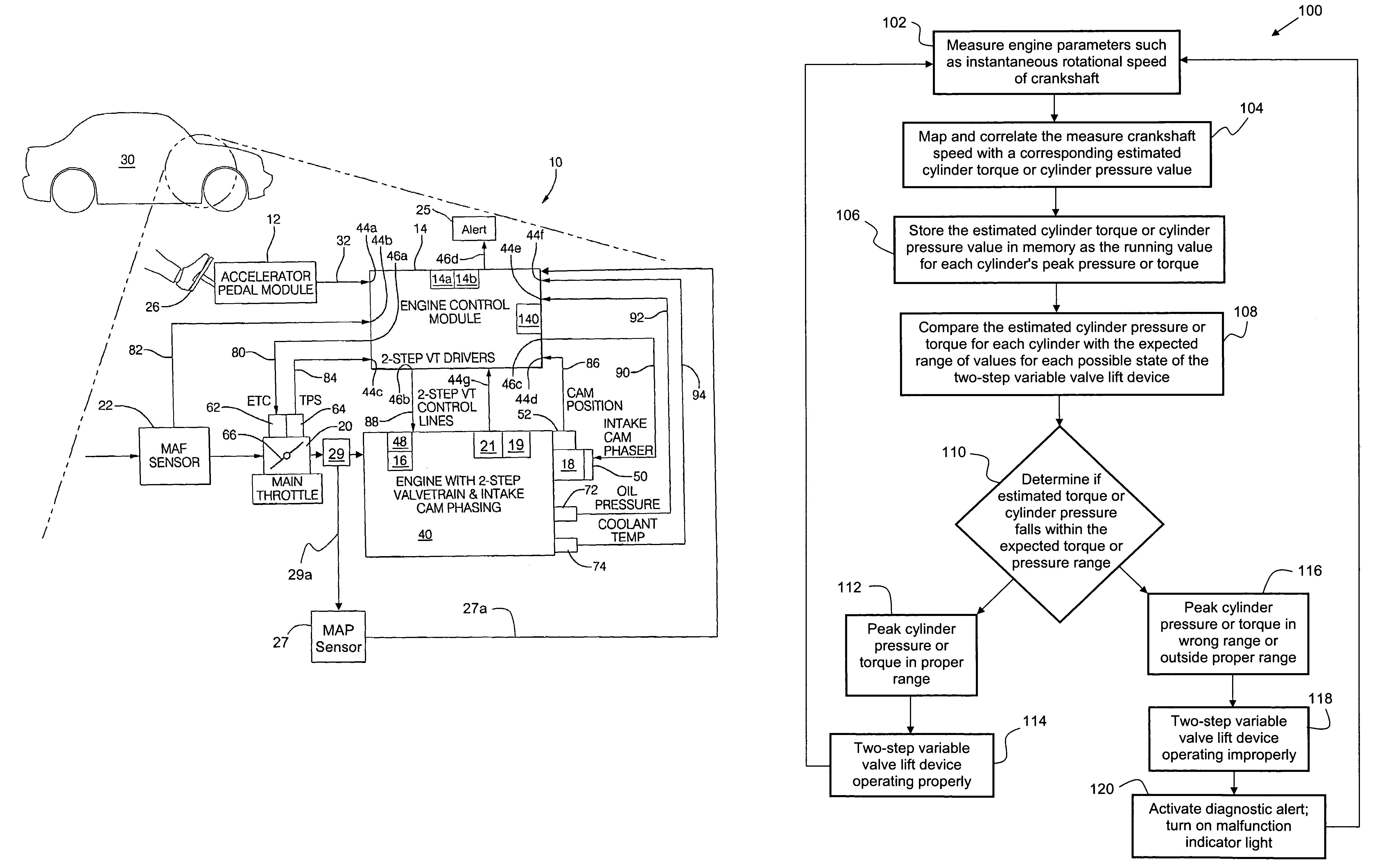
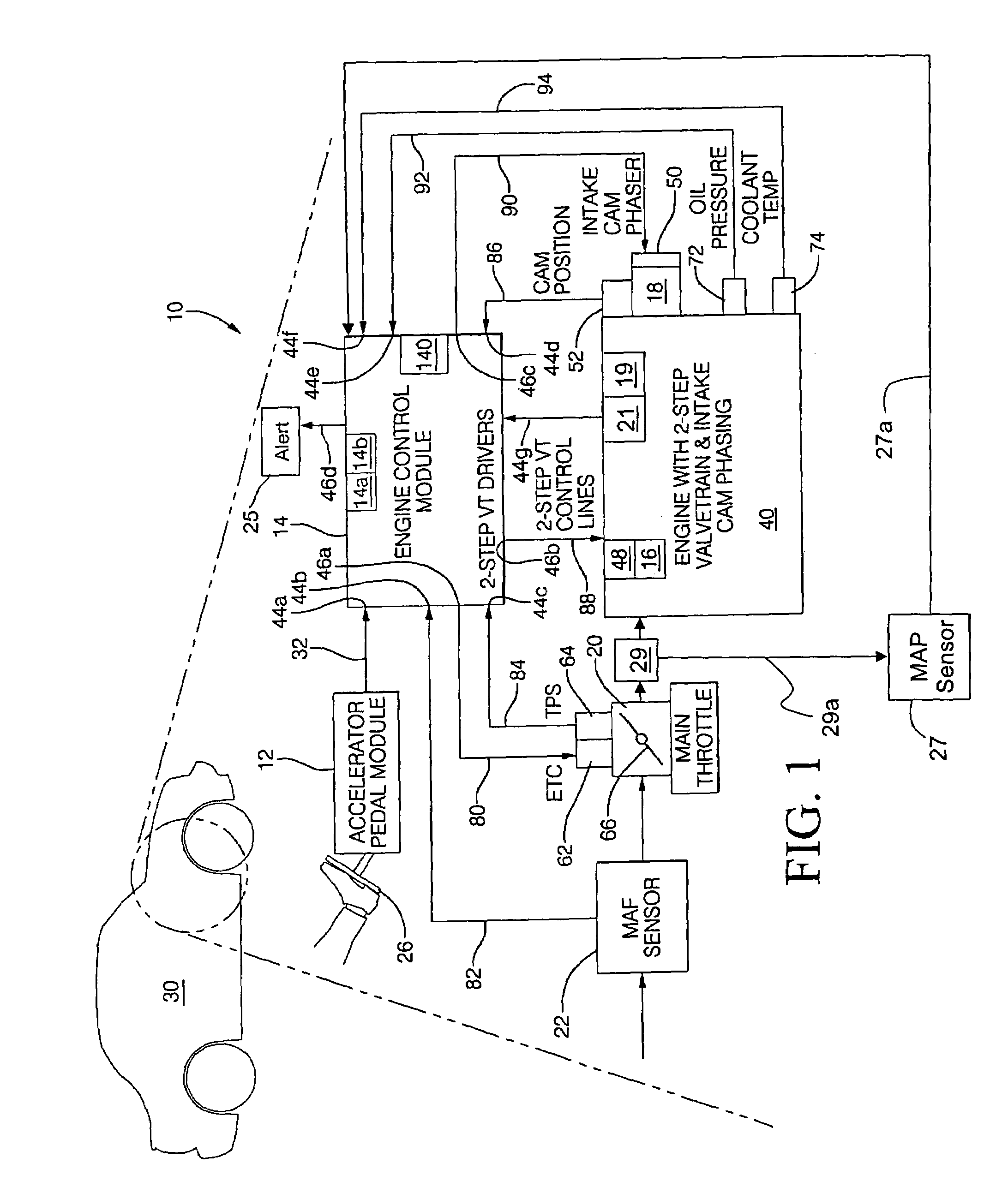
[0013]Generally, as will be described more particularly hereinafter, the method of the present invention is directed to determining whether a two-step variable valve lift device is operating in the improper mode of operation. In particular, the method is performed in real-time in the embedded engine or powertrain controller and monitors existing engine parameters, such as instantaneous cylinder pressure or torque, using preexisting sensors. The measured engine parameters are then compared with an expected range of predetermined values to determine whether one or more of the two-step cam profile switching mechanisms is operating in an improper mode of operation. If it is determined that one or more of the measured engine parameters fall outside of the expected range of predetermined values, an alert is activated to specify that the two-step variable valve lift device is operating in the improper mode of operation.

[0014]The method of the present invention may be implemented by using a...


PUM


Abstract

A method for diagnosing an operational state of a variable valve lift (VVL) device in an engine, wherein the VVL device is capable of operating in two modes of operation. The method includes measuring a rotational speed of an engine crankshaft while the engine is running or cranking, correlating the measured crankshaft speed with an estimated engine cylinder pressure or torque, comparing the estimated engine cylinder pressure or torque with an expected range of engine cylinder pressure or torque values for the two modes of operation for the VVL device, determining if the estimated engine cylinder pressure or torque falls within the expected range of engine cylinder pressure or torque values, and activating an alert if the estimated engine cylinder pressure or torque falls outside the expected range of engine cylinder pressure or torque values to provide notification that the VVL device is operating in an improper mode of operation.

Description

TECHNICAL FIELD[0001]The present invention relates to a method for diagnosing the operational state of a two-step variable valve lift device; more particularly, to a method that compares existing measured engine parameters with an expected range of parameter values to determine if the two-step variable valve lift device is operating in an improper mode of operation; and most particularly, to a method that compares an estimate of the instantaneous cylinder pressure or torque with an expected range of pressure or torque values to determine if the two-step variable valve lift device is operating in an improper mode of operation.BACKGROUND OF THE INVENTION[0002]Historically, the performance of an internal combustion engine has been limited by fixed valve lift profiles, i.e., fixed timing of the opening and closing of the valves relative to the angular position of the engine crankshaft and fixed lift of the valves. However, modern internal combustion engines may utilize one of several me...

Claims


Application Information

Patent Timeline
IPC IPC(8): F01L1/34
CPCF01L13/0036F02D13/0226F02D35/023F02D41/221Y02T10/40F01L1/047F01L1/185F01L2105/00F01L2800/00Y02T10/18F02D13/0238F02D2041/001F02D2200/1004F01L2800/12F01L2305/00Y02T10/12
Inventor WATERS, JAMES P.DARROW, JON C.
Owner DELPHI TECH IP LTD
Why Eureka
Try Eureka