Fuel tank

a fuel tank and tank body technology, applied in the field of fuel tanks, can solve the problems of high cost of activated carbon filters, the housing materials used in modern activated carbon filters are not able to withstand contact with liquid fuel, and the vapor of fuel cannot pass into the environment, so as to simplify the assembly of the fuel tank according to the invention, the effect of increasing the number of connection points

Inactive Publication Date: 2006-05-23
CONTINENTAL AUTOMOTIVE GMBH
View PDF28 Cites 39 Cited by
  • Summary
  • Abstract
  • Description
  • Claims
  • Application Information

AI Technical Summary

Benefits of technology

[0010]A configuration in which the compensation tank and/or the activated carbon filter forms a preassemblable structural unit with a shell part which forms an upper wall of the fuel tank makes the fuel tank according to the invention particularly simple to assemble.
[0011]Assembly of the fuel tank according to the invention is further simplified if housing parts of the activated carbon filter and/or of the compensation tank are joined by material-to-material bonding. This allows the components of the fuel tank to be, for example, welded without difficulty.
[0012]According to another advantageous refinement of the invention, the number of connection points between the activated carbon filter and the chamber can be kept particularly small if connections for vent lines which are guided into the region above the fuel in the chamber are arranged in housing parts of the activated carbon filter and/or of the compensation tank.
[0013]The chamber requires a line which leads via the activated carbon filter into the environment for the purpose of pressure equalization. Accordin...

Problems solved by technology

Therefore, in the event of a leak or as a result of diffusion and permeation at the connection between the activated carbon filter and the chamber, it is impossible for any fuel vapors to pass into the...

Method used


Image

  • Fuel tank
  • Fuel tank

Examples


Embodiment Construction

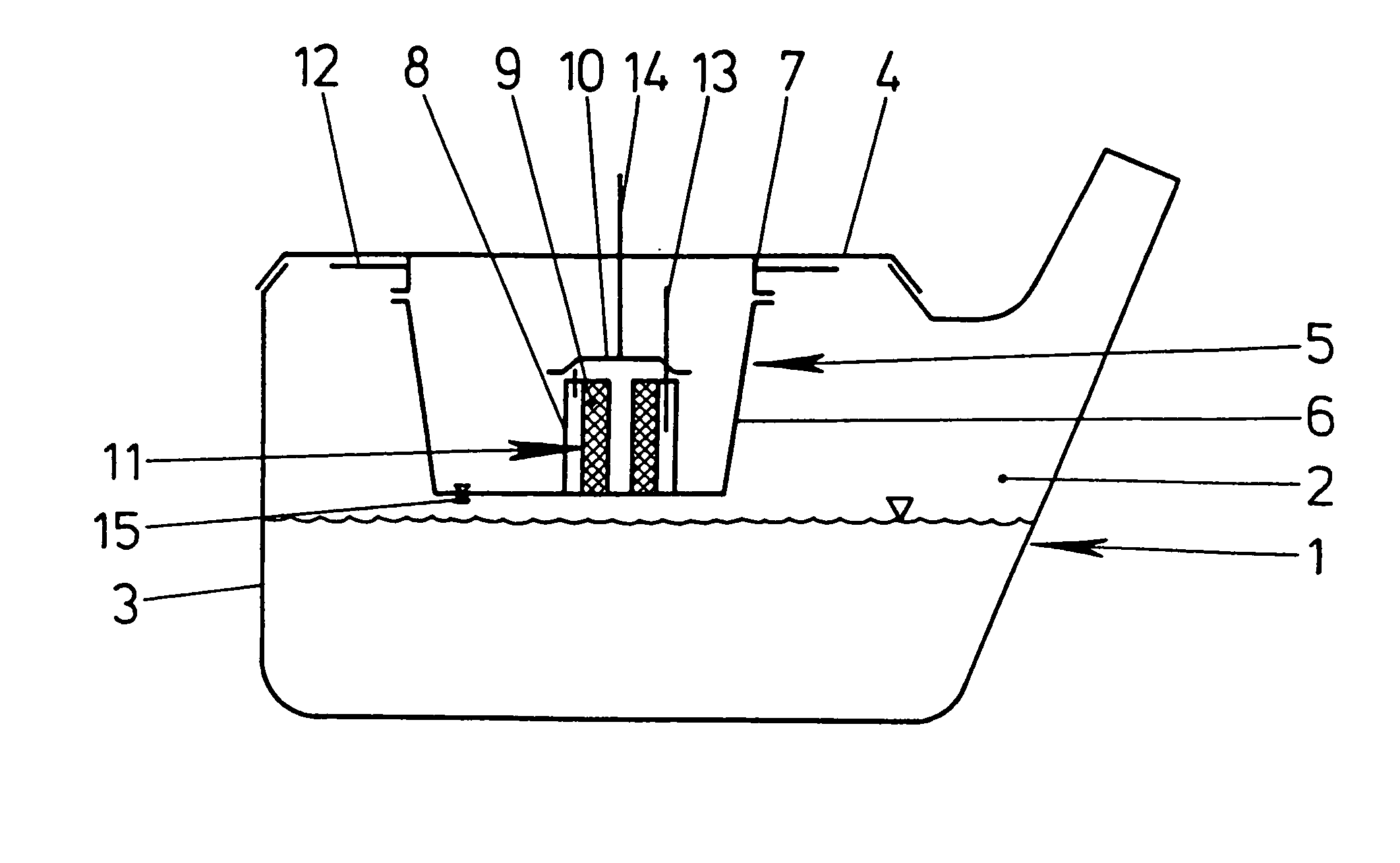
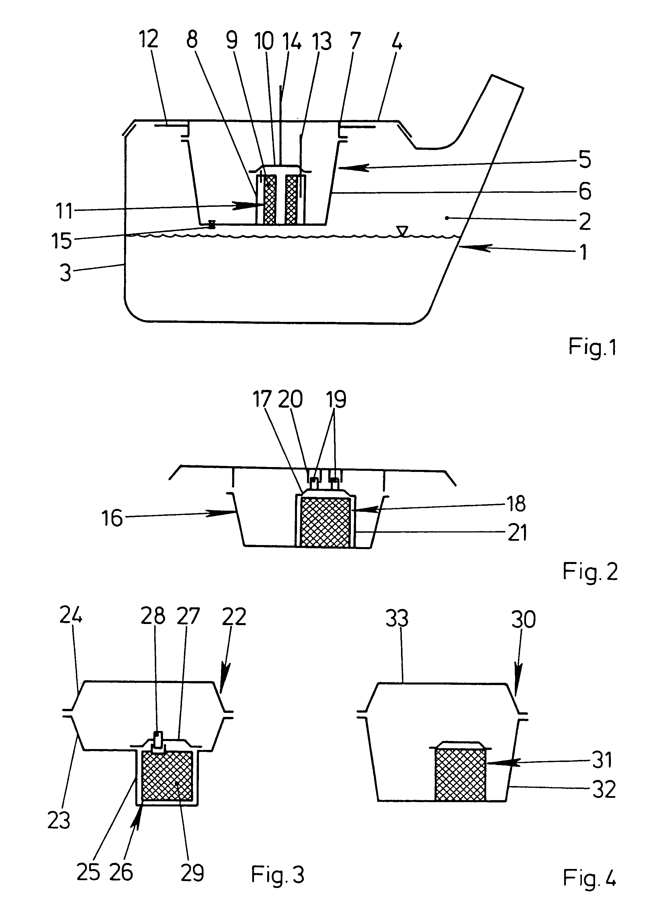
[0023]FIG. 1 diagrammatically depicts a fuel tank in longitudinal section, having a chamber 2 for holding fuel and having two shell parts 3, 4. A compensation tank 5 arranged in the fuel tank 1 has a housing part 6 of pot-shaped configuration and is secured to the upper of the shell parts 4 by material-to-material bonding. The upper shell part 4 has an edge 7 for this purpose. The base region of the pot-shaped housing part 6 of the compensation tank 5 is produced integrally with a housing part 8 of an activated carbon filter 9. The housing part 8 is joined to a cover 10 by material-to-material bonding. The activated carbon filter 9 has a cartridge 11 comprising activated carbon which has been inserted into the housing part 8. Of course, the activated carbon filter 9 can also be produced by activated carbon being introduced into the housing part 8. Vent lines 12 lead into the compensation tank 5 through the upper edge 7 of the shell part 4 of the fuel tank 1. The activated carbon fil...


PUM


Abstract

A fuel tank for a motor vehicle having a chamber delimited by a wall and having an activated carbon filter located to ventilate the volume of the fuel chamber located above the level of fuel in the tank.

Description

BACKGROUND OF THE INVENTION[0001]The invention relates to a fuel tank for a motor vehicle, having a chamber which is delimited by a wall and is used to hold fuel and having an activated carbon filter which is provided for the purpose of ventilating the area of the chamber located above the fuel during refueling and / or during operation.[0002]Fuel tanks of this type are in widespread use in modern motor vehicles and are known in practice. The activated carbon filter has a housing which is made from the plastics polyamide or polypropylene and is partly reinforced with glass fibers and is connected to the chamber via a line which leads through the wall of the fuel tank.[0003]A drawback of the known fuel tank is that fuel vapors can escape into the environment through the connections of the fuel tank and the activated carbon filter, for example through leaks, diffusion or permeation.[0004]The invention is based on the problem of configuring a fuel tank of the type described in the introd...

Claims


Application Information

Patent Timeline
IPC IPC(8): F02M37/04B60K15/035
CPCB60K15/03504Y10T137/86332
Inventor GERHARDT, MARCZAPP, THOMAS
Owner CONTINENTAL AUTOMOTIVE GMBH
Why Eureka
Try Eureka