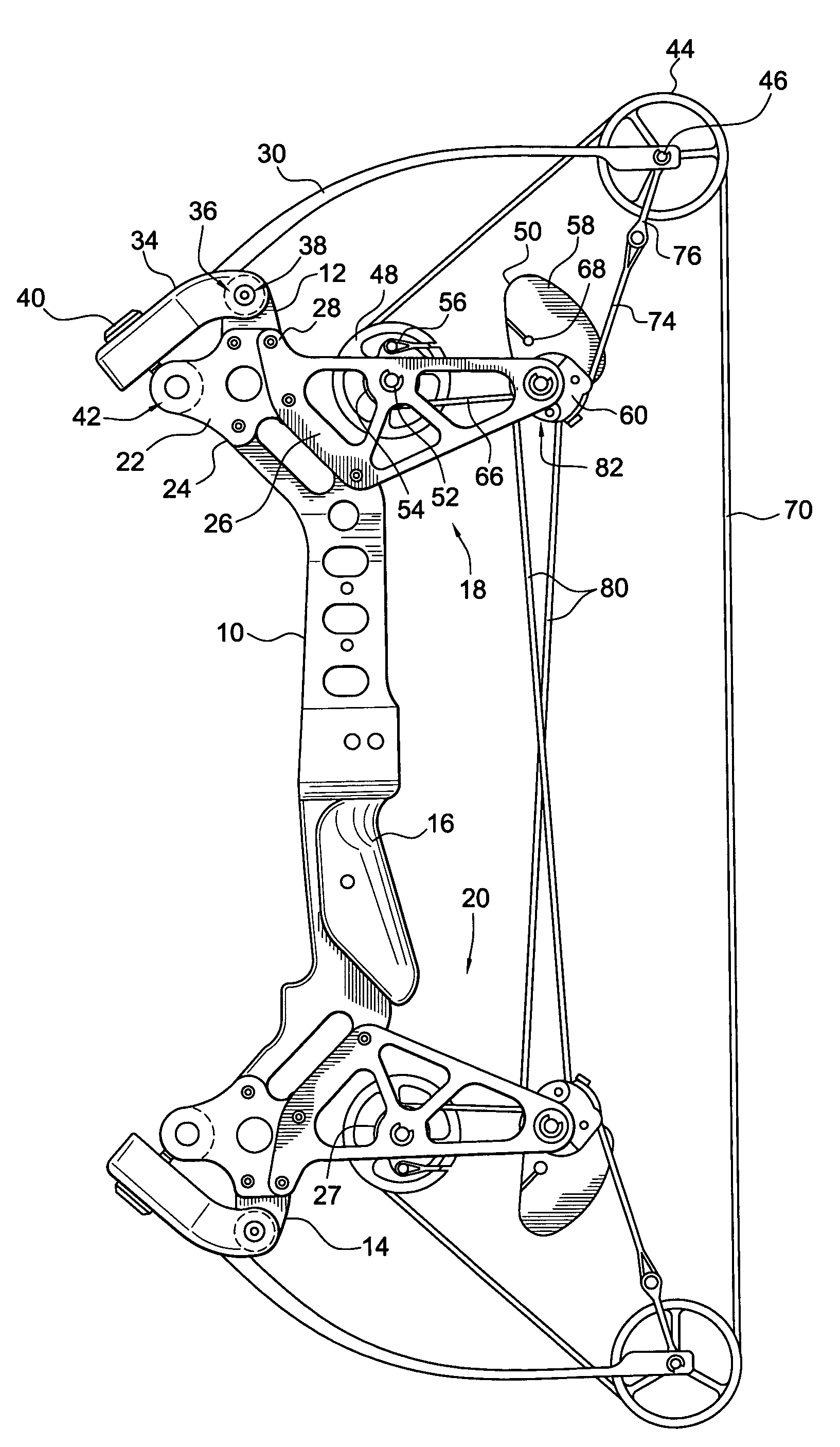
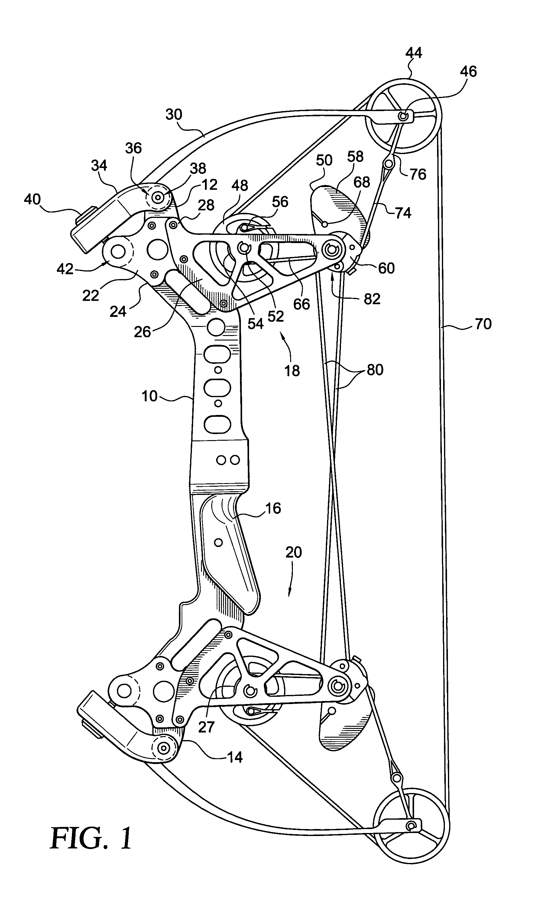
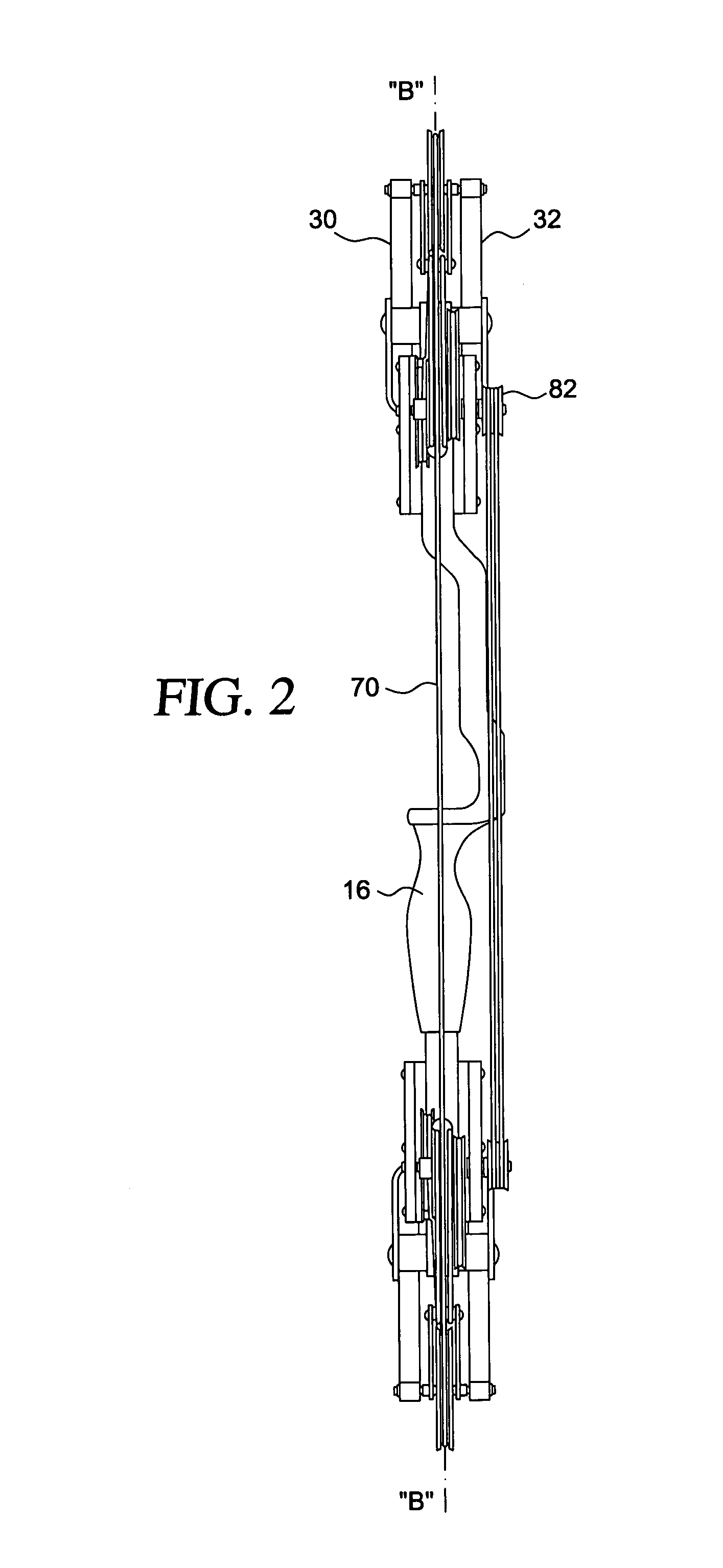
I have found, however, that while my prior patents do indeed provide ways of reducing the overall size of a compound type bow dramatically without sacrificing the ability to provide the longest draw length required, certain aspects of the design act to inhibit performance while other aspects enhance performance, but not enough to compensate for the performance-degrading aspects.
My prior designs could not meet this velocity standard.
However, some characteristics of a bow design tend to enhance accuracy, and some may tend to detract from it.
I have found that while this configuration can fulfil its function of propelling an arrow, satisfactory arrow velocity is not attainable because the flat, wound spring produces high levels of
hysteresis resulting from of the friction between neighboring coils in operation.
In order to benefit from the energy curve produced by a power spring in terms of its relationship to the force / draw characteristics required, the
unsprung mass of the power spring must be so great that, as a contributing factor to the overall
mass weight of the bow, it is impractical as a means of storing energy.
However, although performance was improved, it was still short of acceptable levels because of inherent characteristics that tended to inhibit dynamic efficiency.
Of course, the unfortunate fact remains that the more energy that is available to the arrow means that the more energy is required to draw the bow.
Several factors that affect arrow velocity as well as accuracy and overall performance in a compound type bow have, however, been overlooked or ignored altogether as a result of certain limitations inherent in the conventional design of compound bows.
However, while these principles successfully accomplish the goal of defining and controlling the distribution of
stored energy throughout the draw, they ignore the effect of the ratio of one cam lobe to the other in terms of the effect on the speed of bowstring travel.
However, as the sequence of ratio relationships of one lobe to the other progresses through the launch, the effect of amplification of rate of travel of the bowstring as related to the rate of travel of the cable progressively diminishes and eventually reverses.
In other words, the rate of bowstring travel is constantly slowing down throughout the launch as a seemingly unavoidable result of the design of the cam that is necessary to achieve the desired draw / force characteristics.
Because this aspect of influence upon arrow velocity appears to be unavoidable, it has either been unrecognized or ignored altogether.
Components that are not uniformly loaded or designed specifically to compensate for non-uniform loads tend to deflect or bend under load.
Any such deflection, particularly in the riser, adversely affects both arrow velocity and accuracy.
However, the analysis of
hysteresis in a compound bow cannot be limited to revolving or rotating components alone.
In a compound bow, due to limitations necessary to provide clearance for the arrow, cables, and other elements, a degree of offset and non-balanced loading is perceived to be unavoidable in the design of compound bows.
This imbalance is aggravated by the need to offset that portion of the riser defining the arrow pass and
sight window area.
Further imbalance results from moving the cables that span from the upper to the lower limbs, crossing in the proximity of the arrow path, out of the way in order to provide clearance for the fletching of the arrow.
This
relocation or offset of the cables creates an angular attitude of each cable with respect to the plane of the axle and thus a further load imbalance.
Any deviation from a perfectly
straight path of the nock induces oscillation to the arrow and causes erratic arrow flight.
As yet, however, no compound bow has been designed in which the results of unbalanced loading can be regarded as inconsequential.
As stated above, imbalanced loading of limb tips and subsequent limb twist is an inherent problem of prior art bows, whether of one or two cam design.
On conventional one or two cam bows, this imbalance is a result of the necessity to orient the lobes of the cam(s) such that the bowstring and buss cables will be in their required positions laterally and the fact that the loads in the string and cables constantly change throughout the draw.
This imbalance is further aggravated on conventional bows by the requirement to move the buss cables, which cross from top to bottom in the vicinity of the arrow pass, forcibly toward the string-hand side in order to clear the arrow fletching as the arrow passes the cables.
However, this arrangement created a more pronounced imbalance at the limb tip and thus more pronounced limb twisting.
Yet another aspect related to the tendency of a bow riser to bend or deflect in an undesirable manner relates to the tendency of the upper and the lower portion of the riser to bend back toward the archer about the center or grip portion of the riser as a result of the force of the archer's grip in opposition to the forces of the limbs being deflected by the cables and bowstring.
Deflection or bending in the riser in this manner is likewise detrimental to both performance and accuracy and some attention has been given to the reduction of this effect.
Cable stretch causes undesirable effects in compound bows.
However, owing to the geometry of the bow, the cams do not inherently work in perfect synchronization.
Nevertheless, the one-cam design presents a number of other problems related, in part, to cam timing, nock travel, bowstring and cable angles, unbalanced loading of the riser and other components, cam lean, and subsequent performance characteristics.
However, the amount of reduction is limited because, as the bolt is unscrewed the limb rotates about its pivot point resulting in an angular relationship between the fixed path of the bolt and the plane of the limb.
Although this arrangement provides adequate thread engagement to
resist the forces imposed by the limb on the bolt and riser connection, it provides a limited range of adjustment making it necessary to use a bow press type device to assemble the bow and preload the limbs or to perform maintenance operations such as replacing a bowstring or cables.
Furthermore, this arrangement is subject to the possibility of severe damage to the limbs or other components if the range of adjustment is exceeded.
However, because a certain amount of material of the riser must be available above the openings for the cylindrical bar to
resist the forces transmitted by the bolt, the cylindrical bar is restricted in terms of
diameter thus providing a greatly reduced range of thread engagement and a restricted amount of adjustment in the limb preload.
In fact, due to the limited range of thread engagement in this method, either extreme caution or some mechanical stopping means is required when reducing limb tension by unscrewing the limb bolts in order to avoid a bolt becoming disengaged from its anchor, resulting in an uncontrolled release of limb tension.
In prior bows, ideal nock travel is difficult to achieve for a number of reasons, one being that in most art bows, the nock point on the bowstring is not located at the center point between the limbs.
Thus a greater length of bowstring below the arrow is affected by the draw than the bowstring above the arrow, resulting in an unlevel nock path when viewed from the side of the bow.
Yet another reason for less than ideal nock travel is non-uniformity of components such as the cam and idler: this affects bowstring travel.
However, the aspect of lateral nock travel, as viewed from the front of the bow and in relation to the
vertical plane of the riser, has not been successfully addressed.
Previously, it was mentioned that limb twist and riser deflection adversely affect both accuracy and performance.
In most conventional prior art bow designs, inherent limb twist, cam or idler lean, and
lateral deflection of the riser caused by unbalanced loading results in the bowstring deviating from a straight lateral path.
Upon launch of the arrow, this deviation manifests itself in the form of arrow oscillation affecting both performance and accuracy in an undesirable manner.
With conventional two-cam bow designs, where the arrow nock point is not located at the center of the bowstring between the limbs, cam synchronization is a problem in that the cams must be uniquely designed or provided with some form of adjustment so as to compensate for the unequal lengths of bowstring above and below the arrow nock point so that both cams can rotate in the appropriate relationship to one another and arrive at the proper ending (full draw) position at the appropriate time.
Improper cam synchronization will result in a loss of both accuracy and efficiency.


