Power take-off control system and method

a control system and power take-off technology, applied in the direction of instruments, transportation and packaging, etc., can solve the problems of premature or increased wear on the clutch and other drive line components, and affecting the operation of the power take-off system. , to achieve the effect of shortening the time available for implementing, reducing the rotational speed of the power source or engine, and improving the effect of the

Active Publication Date: 2006-05-23
BLUE LEAF I P INC +1
View PDF21 Cites 71 Cited by
  • Summary
  • Abstract
  • Description
  • Claims
  • Application Information

AI Technical Summary

Problems solved by technology

Generally, as one problem, as a result of any combination of the above factors, if the starting control signal or current value for initiating engagement is too high and / or the subsequent control signals during the fill mode and / or the modulation mode are increased too rapidly for an actual loading condition on the PTO, the engagement can be rougher and / or the rotational speed of the power source or engine can be decreased or droop to an undesirable extent, and even stall.
These are undesirable occurrences as they can cause problems including premature or increased wear on the clutch and other drive line components and even damage.

Method used


Image

  • Power take-off control system and method
  • Power take-off control system and method
  • Power take-off control system and method

Examples


Embodiment Construction

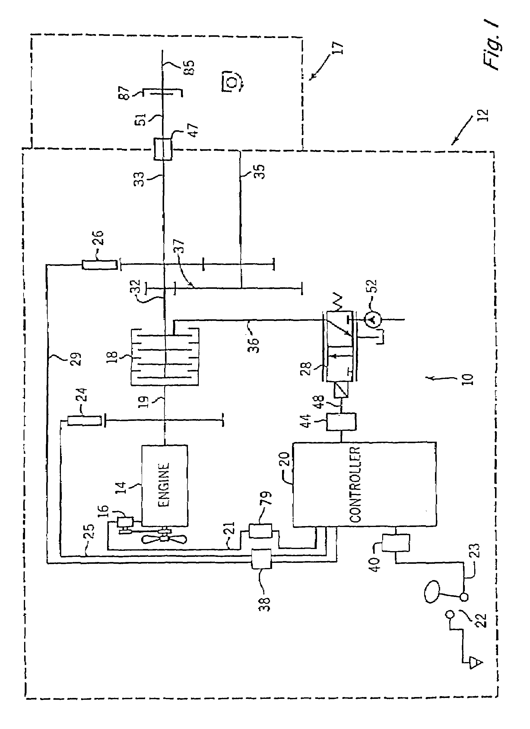
[0030]FIG. 1 depicts an embodiment of a power take-off (PTO) clutch and brake control system 10 for a representative work machine or vehicle, represented by an agricultural vehicle (such as a tractor schematically represented by the dashed line labeled 12) that includes, and is operable according to steps of, the present invention. With the exception of the PTO clutch control system 10, tractor 12 may be a conventional agricultural tractor of the type including a power source which is preferably an engine 14 having conventional accessories such as an alternator 16. Engine 14, in addition to providing power to the drive wheels (not shown) of tractor 12, provides the power to apply rotational motion to a multi-plate hydraulically actuated PTO clutch 18. Depending upon whether PTO clutch 18 is engaged, power from engine 14 may in turn be transmitted to an output shaft 32. Output shaft 32 is shown directly coupled to a 1000 RPM PTO (high speed PTO) shaft 33 and also is shown coupled to ...


PUM


Abstract

A PTO control system and method for engaging a PTO clutch of a vehicle or work machine such as, but not limited to, an agricultural tractor, that can effectively utilize both engine speed and PTO output speed values for determining a predicted and / or actual PTO load and other variable conditions which can effect engagement, and which can responsively calibrate the system for engagement under the load and other conditions and adaptively control applied acceleration and torque during the engagement.

Description

TECHNICAL FIELD[0001]The present invention relates to a power take-off (PTO) control system and method for engaging a PTO clutch of a vehicle or work machine such as, but not limited to, an agricultural tractor, and more particularly, to a PTO control system that can effectively utilize both engine speed and PTO output speed values for determining a predicted and / or actual PTO load and other variable conditions which can effect engagement, and which can responsively calibrate the system for engagement under the load and other conditions and adaptively control applied acceleration and torque during the engagement.BACKGROUND ART[0002]PTOs have long been used on many types of vehicles and work machines, including on agricultural vehicles such as combines and tractors, to provide power for equipment or implements, such as, for agricultural purposes, mowers, balers, forage harvesters and spreaders. Hereinafter, for the present purposes the terms vehicle and work machine are considered th...

Claims


Application Information

Patent Timeline
Patent Type & Authority Patents(United States)
IPC IPC(8): F16H37/00B60K17/28B60K25/00F16D48/06
CPCB60W30/1888F16D48/066B60K17/28Y02T10/84B60W2510/0225B60W2510/0638F16D2500/10437F16D2500/111F16D2500/1112F16D2500/30401F16D2500/30428F16D2500/3067F16D2500/70412F16D2500/70418B60K25/00
Inventor HOU, YANMING
Owner BLUE LEAF I P INC
Why Eureka
Try Eureka