Two stage isolation mount assembly

a technology of isolation mount and mounting plate, which is applied in the direction of shock absorbers, mechanical devices, transportation and packaging, etc., can solve the problems of large relative displacement at maxium load, large clearance between the carrier and the support structure, and relatively tall insulators, so as to smoothly translate the intermittent high amplitude movement and effectively control the maxium load

Inactive Publication Date: 2006-05-23
BASF CORP
View PDF70 Cites 41 Cited by
  • Summary
  • Abstract
  • Description
  • Claims
  • Application Information

AI Technical Summary

Benefits of technology

[0009]Accordingly, the subject invention provides an insulator with a dual tunable resistance for both isolating small amplitude vibrations and controlling the displacements. In particular, the first resistance is calibrated to isolate the vibrations between the frame and vehicle body to provide a smooth ride to the vehicle. In addition, the second resistance is calibrated to smoothly translate the intermittent high amplitude movements of the frame and vehicle body and to effectively control maxiumum displacement to maintain the ride control of the vehicle.

Problems solved by technology

When using linear springs this causes large relative displacement at maxiumum loads.
The relatively tall insulators, however, require large clearances between the carrier and the support structure.
This also creates an undesirable large displacement between the carrier and the support structure which equates to an undesirable large movement (maximum displacement) between the frame and the vehicle body.
In addition, many of the conventional insulators cannot be adequately customized or tuned because of the material and geometrical limitations.
However the total maximum displacement is still too large and the nature and location of the transition from soft to hard spring rate cannot be controlled independent of the properties of polymer.
And thus is not easily tunable.

Method used


Image

  • Two stage isolation mount assembly
  • Two stage isolation mount assembly
  • Two stage isolation mount assembly

Examples


Embodiment Construction

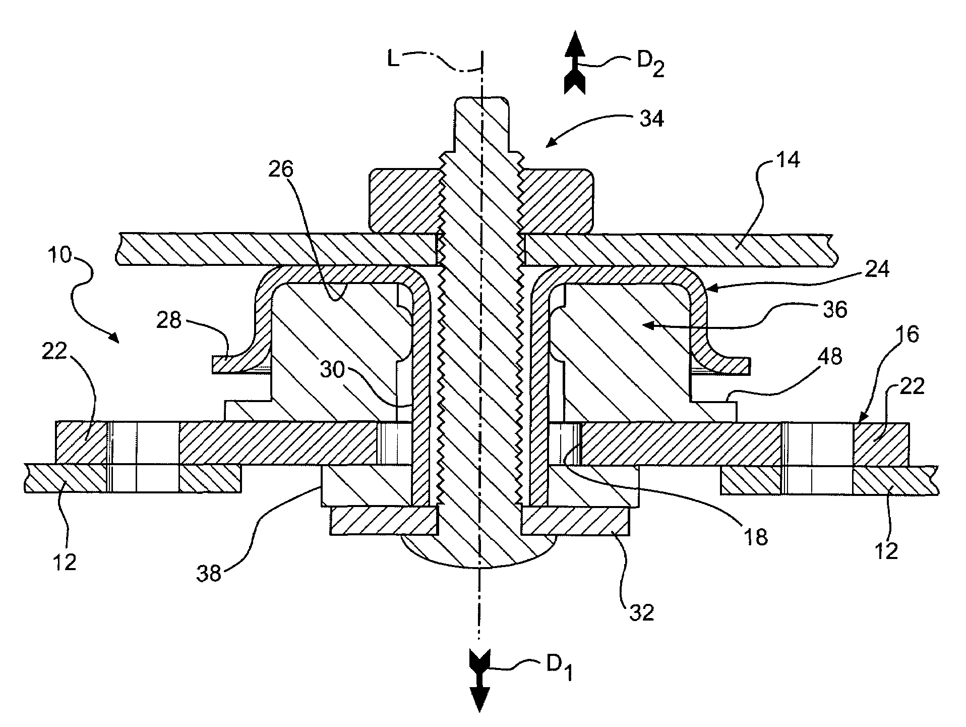
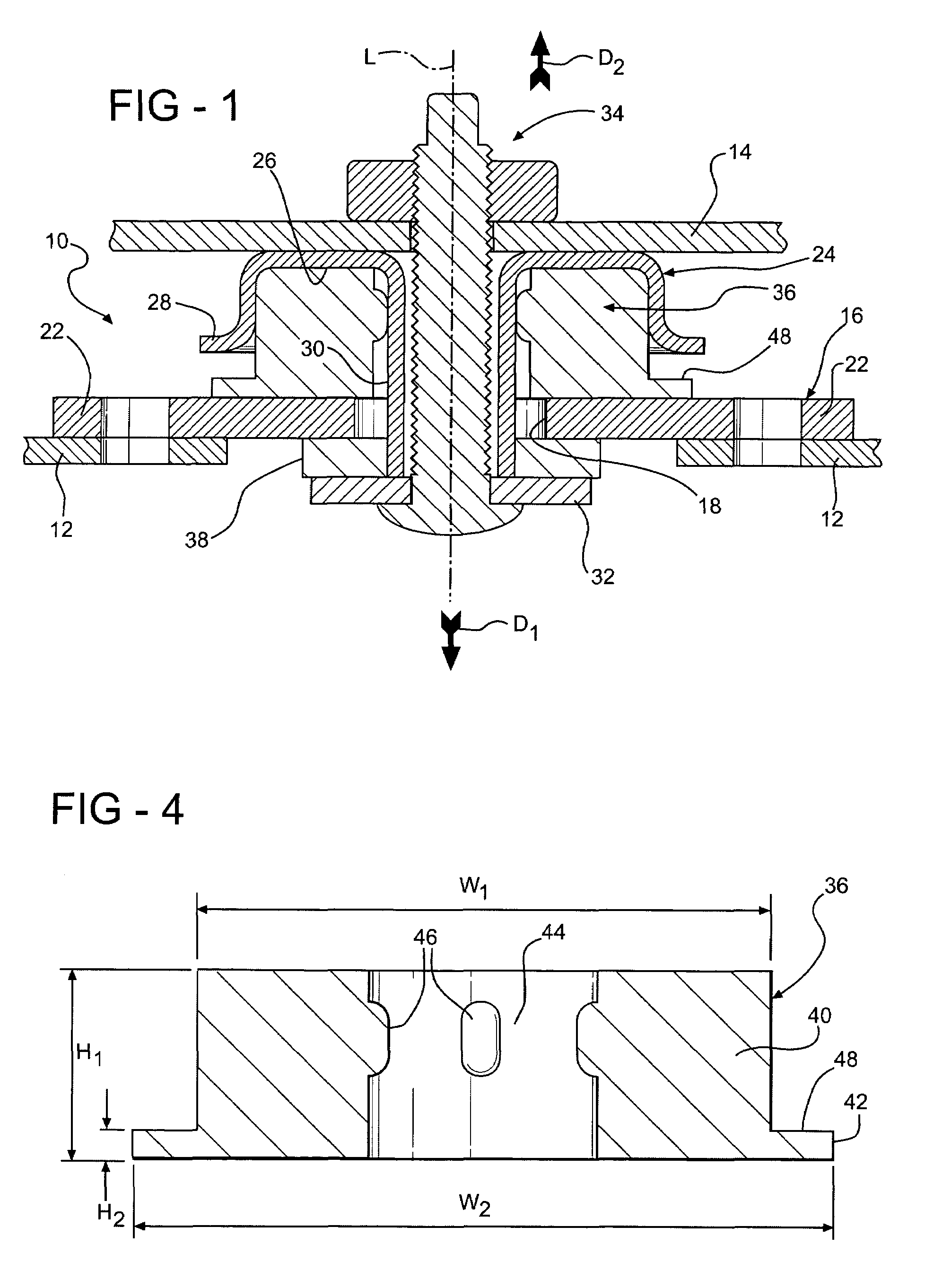
[0018]Referring to the Figures, wherein like numerals indicate like or corresponding parts throughout the several views, a mount assembly 10 in accordance with the subject invention is generally shown at 10 in FIGS. 1 and 2. The mount assembly 10 is shown in a rest state in FIG. 1. In the preferred embodiment, the mount assembly 10 is for use with a vehicle having a frame 12 and a vehicle body 14. For illustrative purposes, only a small fragment of the frame 12 and vehicle body 14 are shown in the Figures. The frame 12 and vehicle body 14 can be of any suitable design or configuration without deviating from the scope of the subject invention. In addition, it should be appreciated by those skilled in the art that the subject invention may be incorporated into different apparatuses and the subsequent discussion relating to a vehicle is but one contemplated environment for the invention.

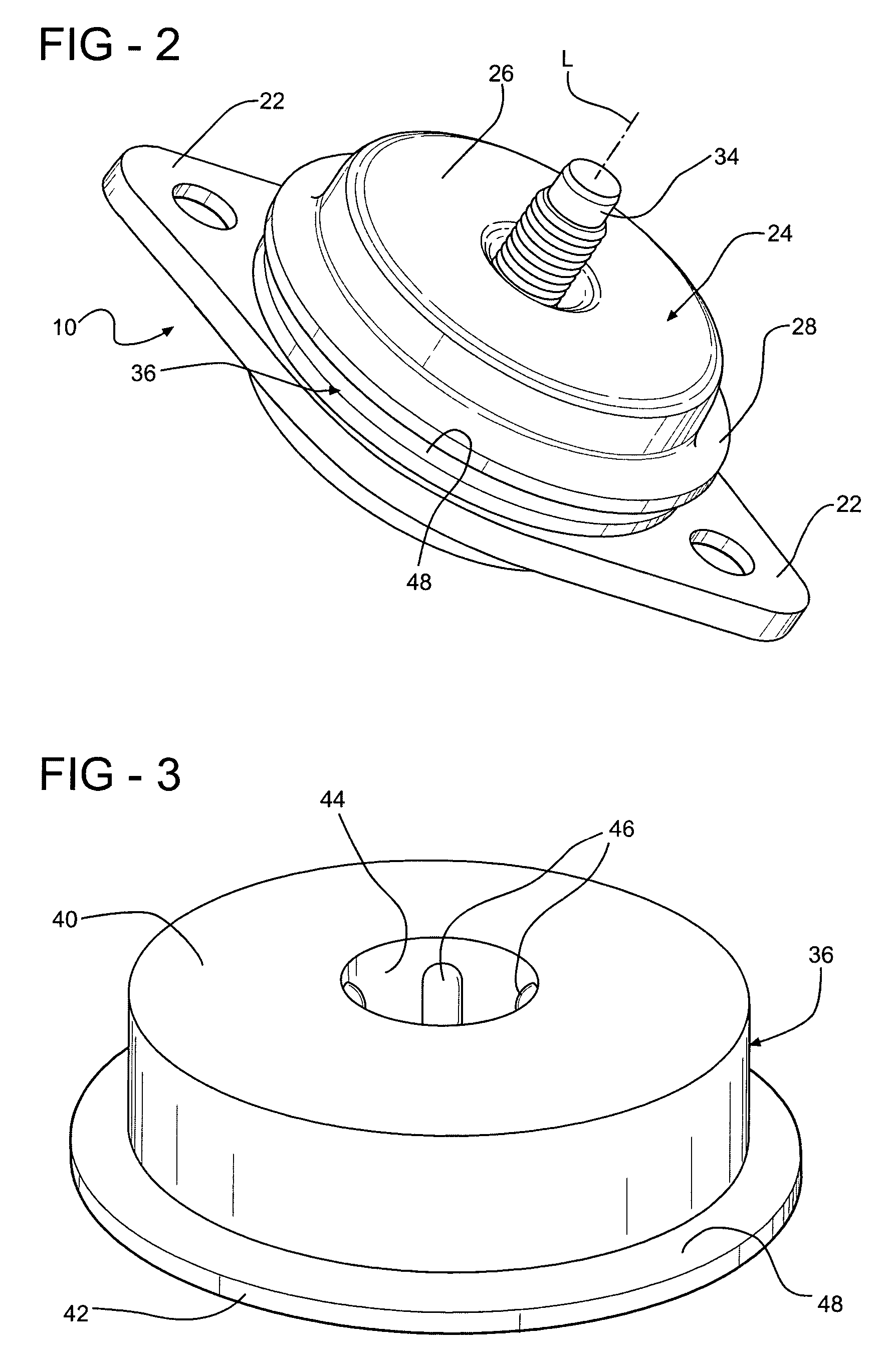
[0019]The mount assembly 10 includes a support structure 16 having an aperture 18. The support struc...


PUM

PropertyMeasurementUnit
height H2aaaaaaaaaa
height H2aaaaaaaaaa
height H2aaaaaaaaaa

Abstract

A mount assembly having a support structure mounted to a frame of a vehicle and a carrier mounted to a vehicle body. The support structure is displaceable relative to the carrier along a line of travel. An insulator is disposed between the support structure and the carrier for coupling the carrier to the support structure. The insulator has a first portion defining a first resistance for isolating the vibrations of the support structure during an application of a first force along a line of travel. The insulator also has a second portion defining a second resistance with the second resistance being greater than the first resistance for controlling the maxiumum displacement of the support structure after the application of the first force and during an application of a second force along the line of travel wherein the second force is greater than the first force. The insulator also provides for tunability of the nature and location of the transition between the first resistance and the second resistance.

Description

BACKGROUND OF THE INVENTION[0001]1. Field of the Invention[0002]The subject invention relates to a mount assembly for a vehicle having a frame and a vehicle body wherein movements of the frame relative to the vehicle body are isolated and / or translated by an insulator.[0003]2. Description of Related Art[0004]Mount assemblies for vehicles are well known in the art. Examples of such assemblies are shown in U.S. Pat. Nos. 6,361,096 and 6,416,102. Each of these assemblies includes a support structure mounted to a frame and a carrier mounted to a vehicle body. The carrier is coupled to the support structure through one or more insulators. The insulators are typically formed of an elastomeric material such as rubber or microcellular polyurethane (MPU).[0005]Currently the insulators are characterized using a load verses deflection curve. An example of such a curve is shown in FIG. 7. The prior art rubber R and prior art urethane C are illustrated along side the subject invention. The slope...

Claims


Application Information

Patent Timeline
Patent Type & Authority Patents(United States)
IPC IPC(8): F16F7/00F16F1/36F16F1/373F16F3/087
CPCF16F3/0873F16F1/3732
Inventor HUPRIKAR, ANAND
Owner BASF CORP
Why Eureka
Try Eureka