C-arm x-ray device

a c-arm and x-ray technology, applied in medical science, diagnostics, electrical equipment, etc., can solve the problems of correspondingly uncomplicated realization, and achieve the effect of convenient and cost-effectiv

a c-arm and x-ray technology, applied in medical science, diagnostics, electrical equipment, etc., can solve the problems of correspondingly uncomplicated realization, and achieve the effect of convenient and cost-effectiv

US7048440B2Active Publication Date: 2006-05-23SIEMENS HEATHCARE GMBH

Image

  • C-arm x-ray device
  • C-arm x-ray device
  • C-arm x-ray device

Examples


Embodiment Construction

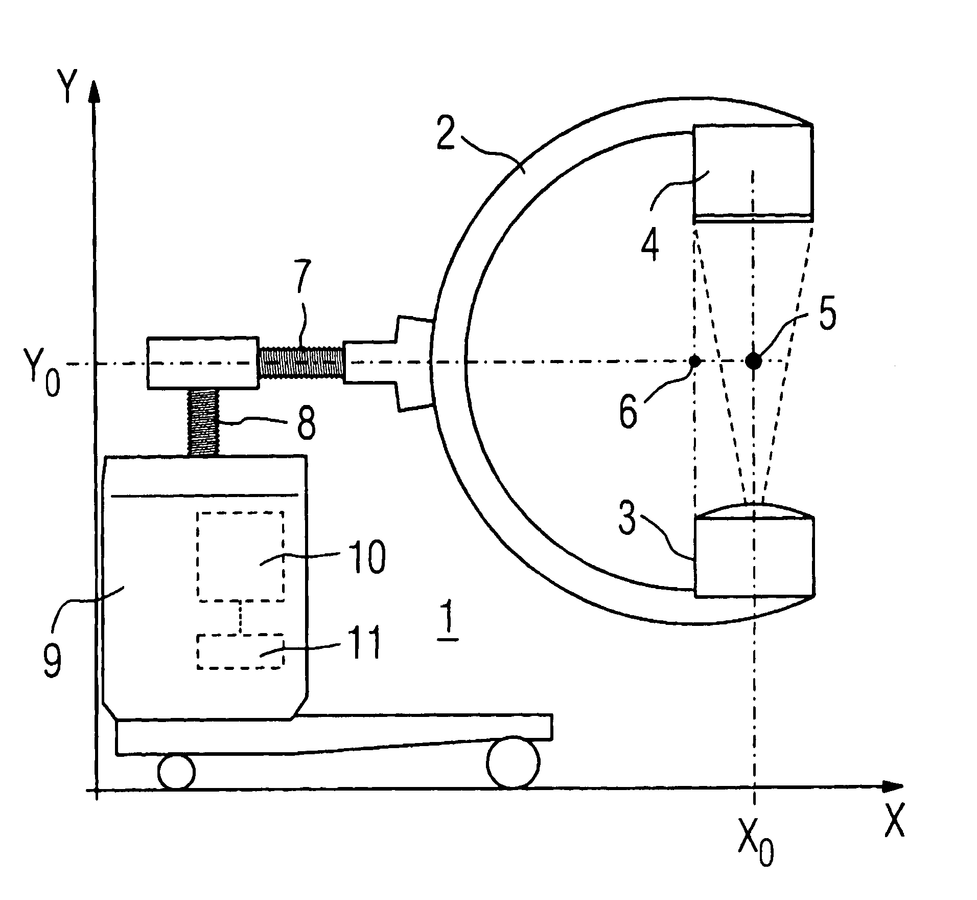
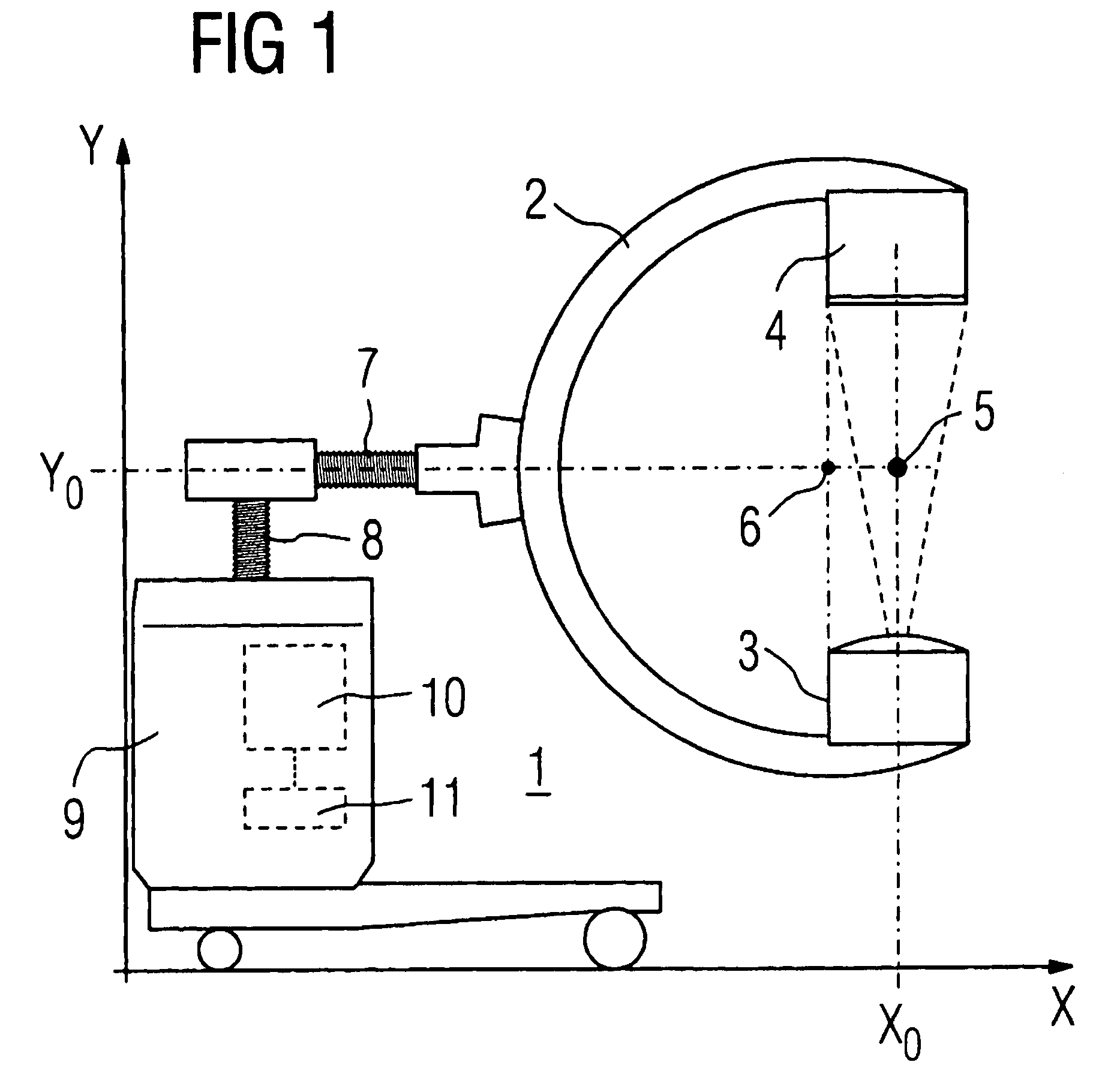
[0018]A C-arm x-ray device 1 with a vertically oriented x-ray beam is shown in FIG. 1. The x-ray beam is indicated as a radiation beam via dashed lines between the x-ray source 3 and the image sensor 4. It runs through the “isocentric point”5 that is likewise indicated in FIG. 1.

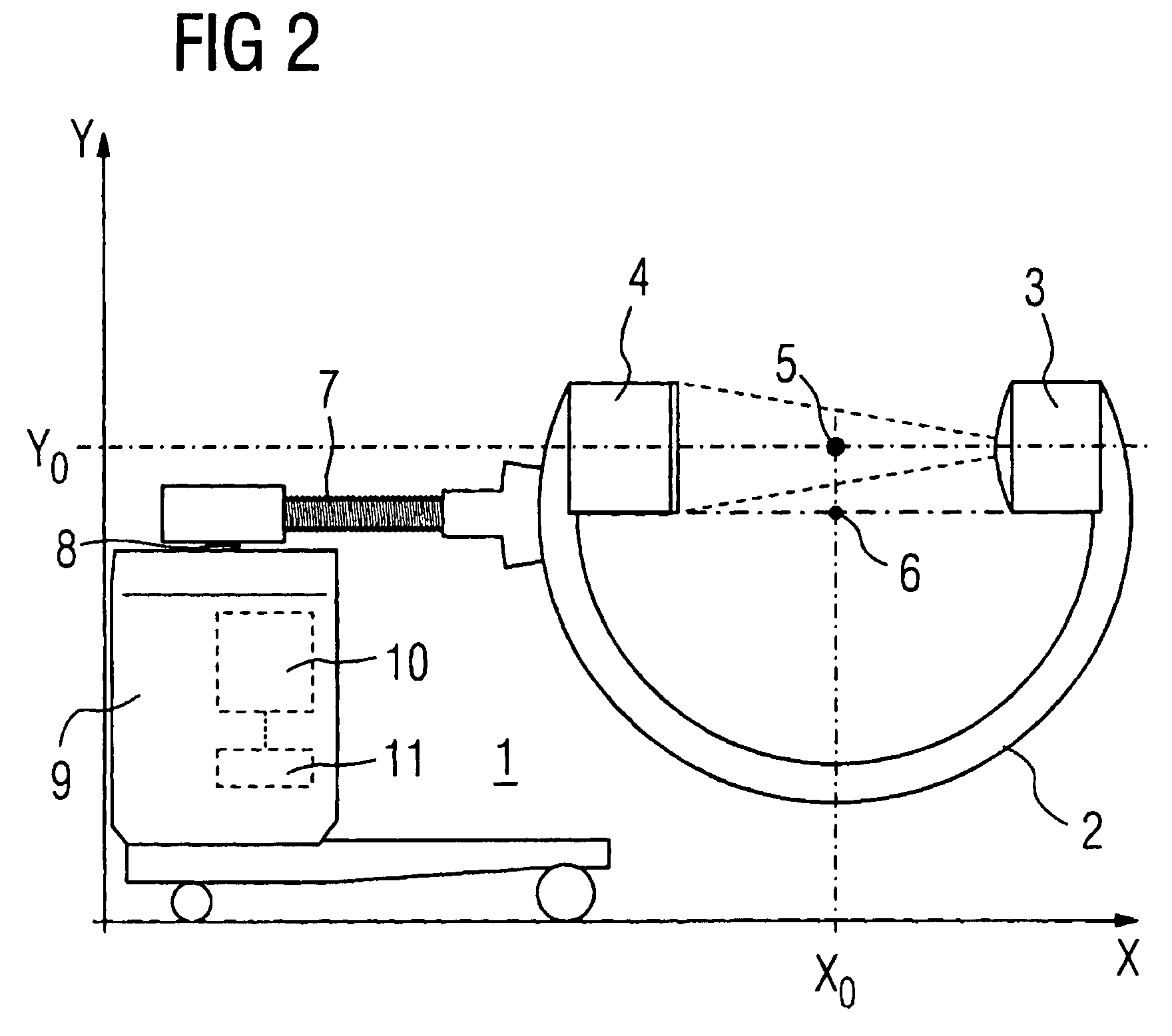
[0019]The C-arm x-ray device comprises a C-arm 2 that is fashioned non-isocentrically. Non-isocentric means that the rotation center 6 for rotation movements of the C-arm 2 is not identical with the isocenter 5. Rather, the rotation center 6 is situated horizontally near the isocenter 5, such that a rotation of the C-arm 2 in the orbital direction would also lead to a rotation of the isocenter 5 around the rotation center 6. This displacement of the isocenter 5 would make impossible the generation of three-dimensional images from various two-dimensional projections that are acquired via different orientations of the x-ray beam.

[0020]In order to overcome this problem, the C-arm x-ray detector 1 comprises a ho...


PUM


Abstract

The invention concerns a C-arm x-ray device with a non-isocentric C-arm on which an x-ray source is positioned and that can be orbitally or angularly rotated, whereby the C-arm x-ray device comprises a device fashioned to horizontally adjust the C-arm (which enables an adjustment of the C-arm within the plane of the C-arm) and a device fashioned to vertically adjust the C-arm, where the horizontal adjustment device and the vertical adjustment device are fashioned such that they can automatically move the central x-ray beam of the x-ray source back into the isocenter, given an orbital or angulatory rotation of the C-arm via the horizontal and vertical adjustment device. An appertaining method is also provided.

Description

CROSS REFERENCE TO RELATED APPLICATIONS[0001]The present application claims the benefit of U.S. Provisional Application No. 60 / 454,053, filed Mar. 12, 2003.BACKGROUND OF THE INVENTION[0002]The invention concerns a C-arm x-ray device for 3D imaging.[0003]X-ray detectors are used to generate images of a transirradiated subject or body. The x-rays pass through the subject or patient and then strike an image detector on which they form a two-dimensional projection of the transirradiated volume.[0004]Three-dimensional image data can be generated using a plurality of two-dimensional projections of the same x-ray volume. The individual two-dimensional image data are evaluated using a computer to generate a three-dimensional image. For this, the two-dimensional image data must exist digitized, which is why digital image sensors are used and not analog film / foil systems. Digital image sensors directly generate digital, pixelated image data as soon as x-ray radiation is incident upon them. Th...

Claims


Application Information

Patent Timeline
23 May 2006
Publication
US7048440B2
IPC
H05G1/02; A61B6/00
CPC
A61B6/4441; A61B6/4405
Inventors
GRAUMANN, RAINER; HEINZE, UDO