Gas turbine stator

a technology of stator and gas turbine, which is applied in the direction of efficient propulsion technology, machines/engines, liquid fuel engines, etc., can solve the problems of increasing the temperature of the pressurised, the internal labyrinth gland cannot stop some of the hot air present, and the lagging gland cannot stop all the air leakage through the chamber

Inactive Publication Date: 2006-05-23
SN DETUDE & DE CONSTR DE MOTEURS DAVIATION S N E C M A
View PDF9 Cites 31 Cited by
  • Summary
  • Abstract
  • Description
  • Claims
  • Application Information

AI Technical Summary

Benefits of technology

[0015]According to this particular embodiment implementing piercings to allow for the evacuation of discharge air, an advantage of the invention resides in the reduction in manufacturing costs by using an existing part instead of adding pipes as per the prior art. This stator according to the invention also participates in the lightening of the injectors, as well as the lengthening of the service life of the stator due to the absence of welding of the pipes as is of common practice.
[0016]Preferably, the piercings implemented to accomplish the means of evacuating discharge air are carried out in the solid part of the blades constituting the first injection means.
[0017]According to a particular embodiment of the invention, the support of a part of the internal labyrinth gland comprises the first injection means. This support has a honeycomb structure alternatively made of cavities and blocks of material. The cavities are thus intended to lead to the evacuation means whereas the blocks of material comprise the third injection means.
[0018]Advantageously, the stator according to the invention can then have a crossover system for three flows of air assembled in a single part capable of being made in a single casting. We note that this particular configuration of the invention makes it simple to assemble the different elements of the stator.

Problems solved by technology

However, even though the labyrinth glands are commonly used to render the pressurised chamber leakproof, as notably disclosed in the document FR 2744761, these labyrinth glands cannot stop all the air leaks through this chamber.
In particular, the internal labyrinth gland cannot stop some of the hot air present outside the pressurised chamber from penetrating into the latter.
This consequently generates an increase in temperature of the pressurised chamber, and thus a reduction in the efficiency of the cooling system of the rotor.

Method used


Image

  • Gas turbine stator
  • Gas turbine stator
  • Gas turbine stator

Examples


Embodiment Construction

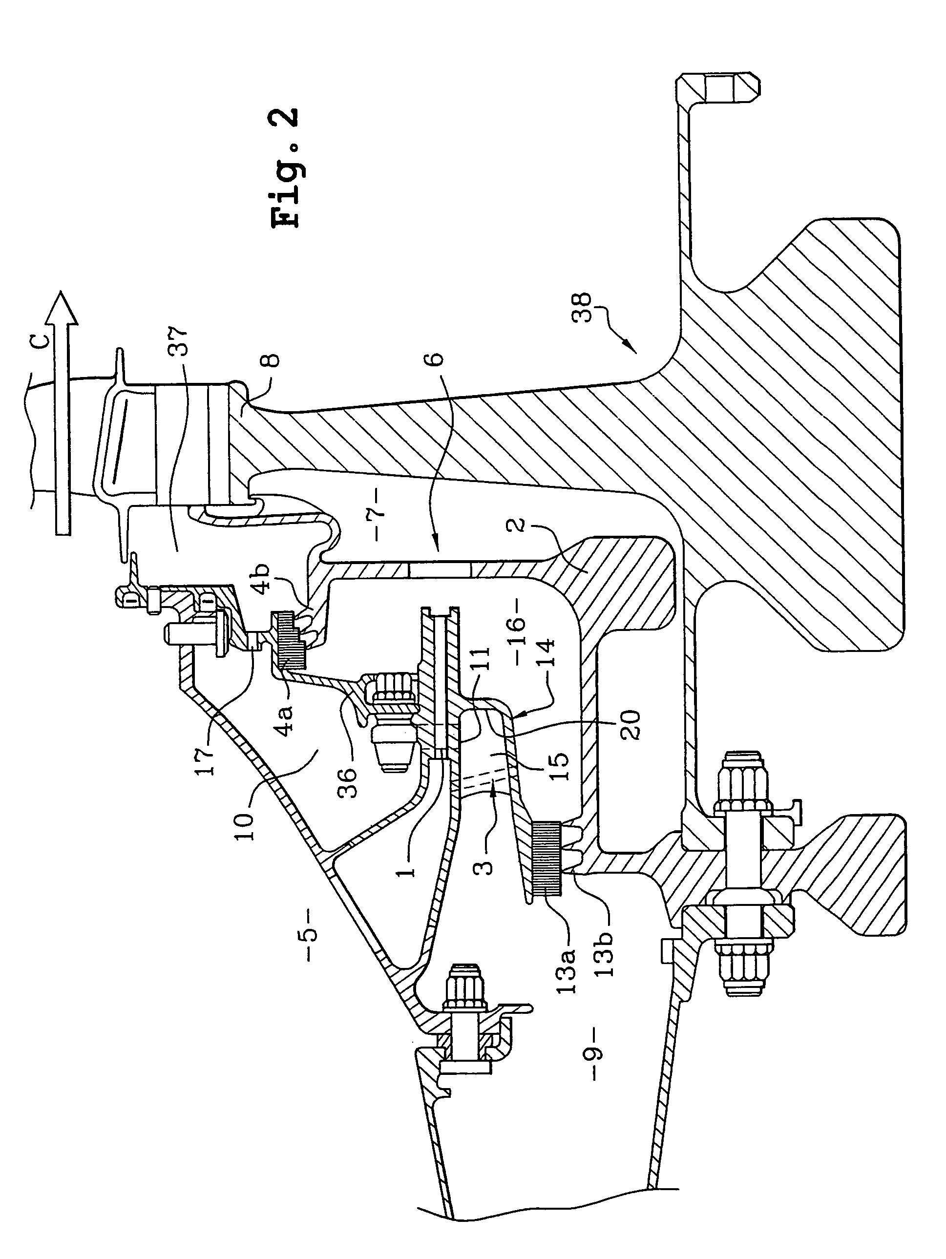
[0024]In reference to FIG. 2, we see one part of a turbine engine notably comprising a stator according to the invention. This stator firstly comprises a pressurised chamber 16 delimited by different elements. Among these elements there is an external labyrinth gland 4a and 4b as well as an internal labyrinth gland 13a and 13b. These two internal and external labyrinth glands 13a, 13b, 4a and 4b are respectively held by a support 14 fixed to the wall of a stator cavity 5 and another support 36 fixed to this support 14. The internal labyrinth gland 13a and 13b partly delimits a boundary between the pressurised chamber 16 and a first cavity 9 adjacent to it, whereas the external labyrinth gland 4a and 4b partly delimits a boundary between the pressurised chamber 16 and a second cavity 10 also adjacent to it. The first and second cavities 9 and 10 are themselves separated by the support 14. It is to be noted that the stator has, downstream from the second cavity 10 in the direction of ...


PUM


Abstract

A gas turbine stator including at least a first injector providing a passage for a main cooling air stream into a pressurized chamber. An evacuation mechanism discharges air coming from an internal labyrinth gland of a first cavity towards a lower-pressure second cavity. A second injector evacuates the air contained in the second cavity towards a main duct. The stator further includes a third injector designed to generate an overpressure close to the internal labyrinth gland in the pressurized chamber.

Description

TECHNICAL FIELD[0001]The technical field of this invention is that of gas turbines, such as axial-flow turbine engines, comprising a stator notably intended to supply air to other elements of the gas turbine. This stator in particular, is a mechanical unit, which allows relatively cool air to be supplied to the blades of the high-pressure turbine, this air intended notably to cool a part of the rotor being drawn from the bottom of the combustion chamber.STATE OF THE PRIOR ART[0002]In well-known embodiments of gas turbine stators of the prior art, we usually find an element such as a main injector which makes it possible to accelerate the air drawn from a cavity in the stator, a retainer for guiding the air down to the blades of the high-pressure turbine, as well as different air circuits making it possible to calibrate all the airflows throughout the system. These airflows are then injected into different cavities consequently making it possible to limit the rise in temperature of t...

Claims


Application Information

Patent Timeline
Patent Type & Authority Patents(United States)
IPC IPC(8): F01D25/12F01D11/04F01D1/00F01D5/08F01D11/00F01D11/02F01D25/00F02C7/28
CPCF01D5/081F01D11/001F05D2260/6022Y02T50/676Y02T50/673Y02T50/60F01D5/08
Inventor ARILLA, JEAN-BAPTISTEGALLAND, ALAINHACAULT, MICHEL GERARD PAULMAFFRE, JEAN-PHILIPPE
Owner SN DETUDE & DE CONSTR DE MOTEURS DAVIATION S N E C M A
Why Eureka
Try Eureka