Female terminal fitting and connector provided therewith

a technology for female terminals and connectors, which is applied in the manufacture of coupling contact parts, coupling device connections, coupling contact parts, etc., can solve the problems of insufficient locking force and achieve the effects of preventing excessive deformation of resilient contact parts, preventing escape, and enhancing locking for

Inactive Publication Date: 2006-05-23
SUMITOMO WIRING SYST LTD
View PDF12 Cites 38 Cited by
  • Summary
  • Abstract
  • Description
  • Claims
  • Application Information

AI Technical Summary

Benefits of technology

[0010]The disposition of the engaging portion on an outer surface of the main portion ensures a large area of engagement with the lock. Thus, a sufficient locking force is achieved. On the other hand, the engaging portion is folded back at the front edge of the side plate and the folded part can be rounded. This rounded part contacts the lock as the female terminal fitting is inserted. Thus, resistance is low and a smaller inserting force can be realized.
[0013]The lock intrudes at the inner side of the slanted surface and is prevented from escaping by sliding on the locking surface. Thus, the locking force can be enhanced further.
[0014]One side plate preferably is embossed to project in near an area where the engaging portion is folded. The embossment forms an excessive deformation preventing portion that contacts the resilient contact piece to prevent excessive deformation of the resilient contact piece.
[0015]When the lock presses the engaging portion, a force acts to turn the engaging portion and to deform the side plate that has the engaging portion. However, the excessive deformation preventing portion increases the section modulus of the one side plate and reinforces the one side plate. Thus, strength against the deformation of the engaging portion following this one side plate can also be increased.
[0016]At least one retaining portion may be inserted into a side plate of the main portion adjacent the one side plate and at a lateral edge of the engaging portion. The retaining portion increases the strength of the engaging portion in a buckling direction and helps to retain the shape of main portion.

Problems solved by technology

Thus, a sufficient locking force may not be ensured.

Method used


Image

  • Female terminal fitting and connector provided therewith
  • Female terminal fitting and connector provided therewith
  • Female terminal fitting and connector provided therewith

Examples


Embodiment Construction

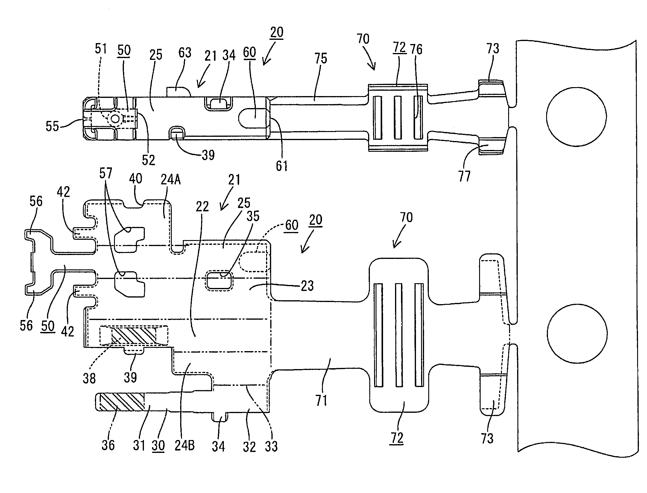
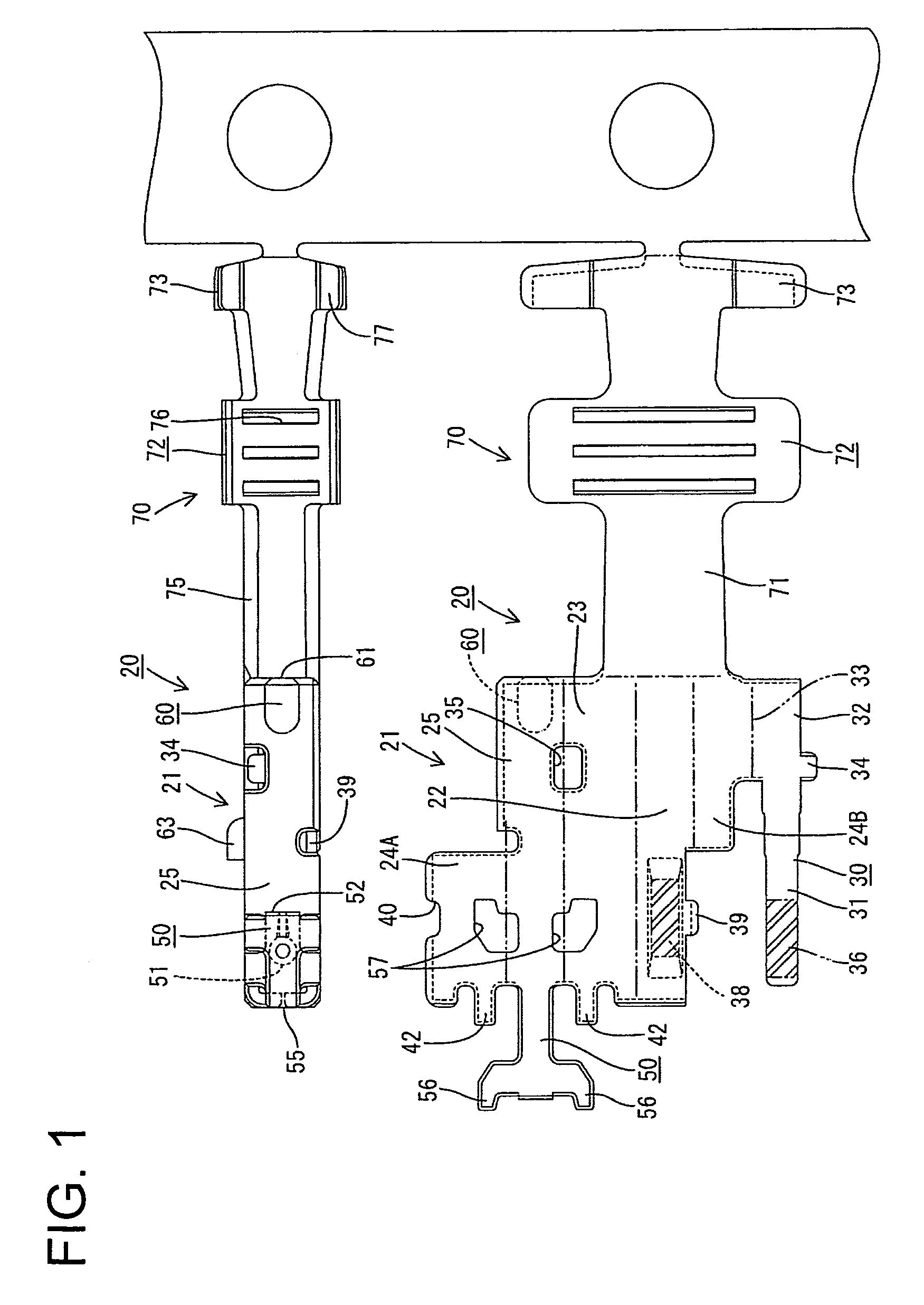
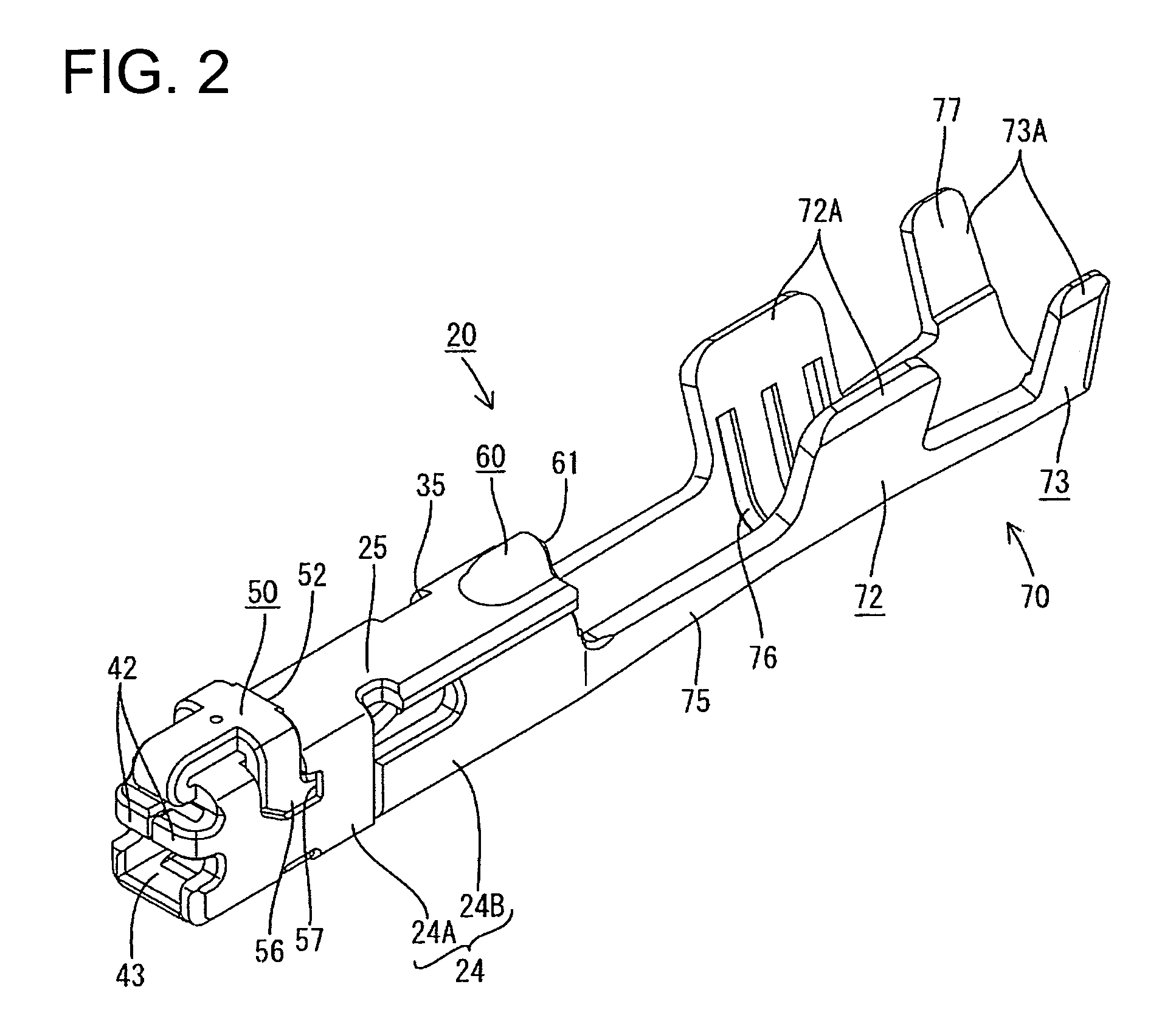
[0032]A female terminal fitting according to the invention is identified by the numeral 20 in FIGS. 1 to 11 and is formed by stamping or cutting an electrically conductive metal plate to define the blank shown at the lower side of FIG. 1. The blank then is bent, folded and / or embossed to form the female terminal fitting 20 shown at an upper side of FIG. 1 and in FIG. 2. The female terminal fitting 20 has opposite front and rear ends. A rectangular tubular main portion 21 is formed at the front end and is configured to receive a mating male terminal fitting Mt (see FIG. 11) inserted from the front. A wire-connecting portion 70 is formed at the rear of the female terminal fitting. The wire-connecting portion 70 is crimped into connection with the end of the insulated wire 10 and then female terminal fitting 20 is accommodated in a female housing 15.

[0033]As shown in FIG. 9, cavities 16 are arranged at upper and lower stages and penetrate the female housing 15 along forward and backwar...


PUM


Abstract

A female terminal fitting (20) has a main portion (21) that can be inserted into a cavity. An engaging portion (50) for engaging a lock (17) in the cavity is folded back from the front of the main portion (21). The fold (55) is rounded and contacts the lock (17) when the terminal fitting (20) is inserted into a cavity. Thus, resistance to insertion is low. The engaging portion (50) is distanced from an opposed surface (25) of the main portion (21) by an embossment (51). Thus, a large area of engagement with the lock (17) exists. A slanted surface (53) is formed at a corner of a locking surface (52) closer to the ceiling plate (25). Thus, the leading end of the lock (17) intrudes at the inner side of the slanted surface (53) to prevent the lock (17) from escaping.

Description

BACKGROUND OF THE INVENTION[0001]1. Field of the Invention[0002]The invention relates to a female terminal fitting and to a connector provided therewith.[0003]2. Description of the Related Art[0004]Japanese Unexamined Patent Publication No. 2002-175849 discloses a female terminal fitting that has a rectangular tubular main portion. A resilient contact is provided in the main portion for contacting a mating male terminal fitting. The female terminal fitting is inserted into a cavity of a connector housing from behind. A resin lock is formed in the cavity and engages a locking hole in a side plate of the main portion of the female terminal fitting to hold the female terminal fitting in the cavity. Miniaturization of the female terminal fitting has reduced a margin of the resin lock that is fit into the main portion. Thus, a sufficient locking force may not be ensured. Accordingly, a proposal has been made to form an engaging portion on an outer surface of the main portion and to engag...

Claims


Application Information

Patent Timeline
Patent Type & Authority Patents(United States)
IPC IPC(8): H01R13/40H01R13/11H01R13/115H01R13/42H01R13/422H01R13/436H01R43/16
CPCH01R13/113H01R43/16H01R13/4362H01R13/4223
Inventor TABATA, MASAAKIKOJIMA, EIJI
Owner SUMITOMO WIRING SYST LTD
Why Eureka
Try Eureka