
Materials and construction for a tamper indicating radio frequency identification label

a radio frequency identification and material technology, applied in the field of materials and construction for tampering radio frequency identification labels, can solve problems such as not allowing remote determination

Inactive Publication Date: 2006-05-23
MAJKOKH CORP +1
View PDF17 Cites 168 Cited by
  • Summary
  • Abstract
  • Description
  • Claims
  • Application Information

AI Technical Summary

Benefits of technology

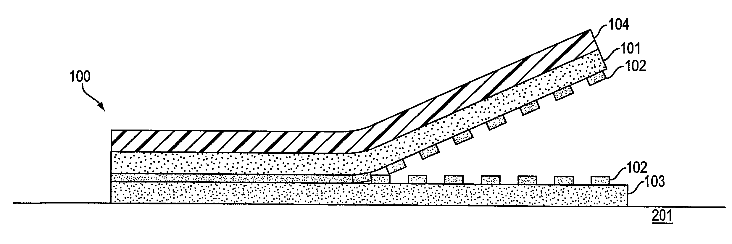
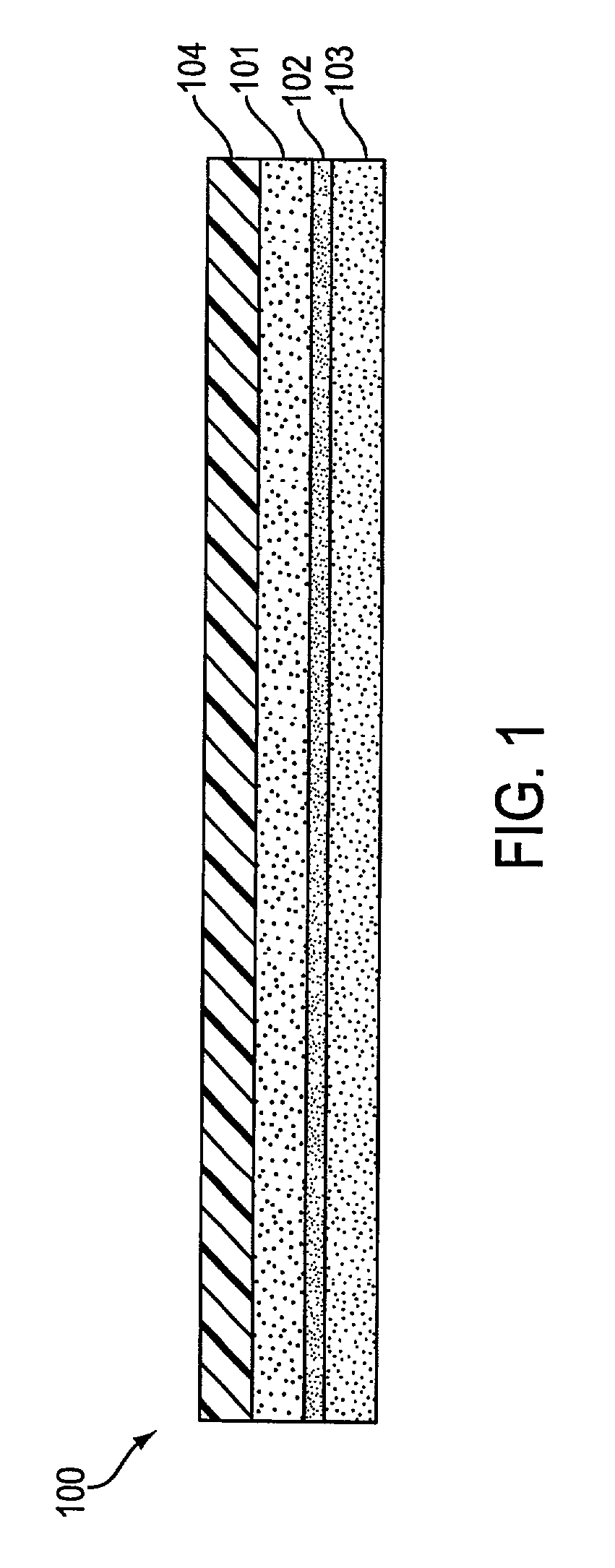
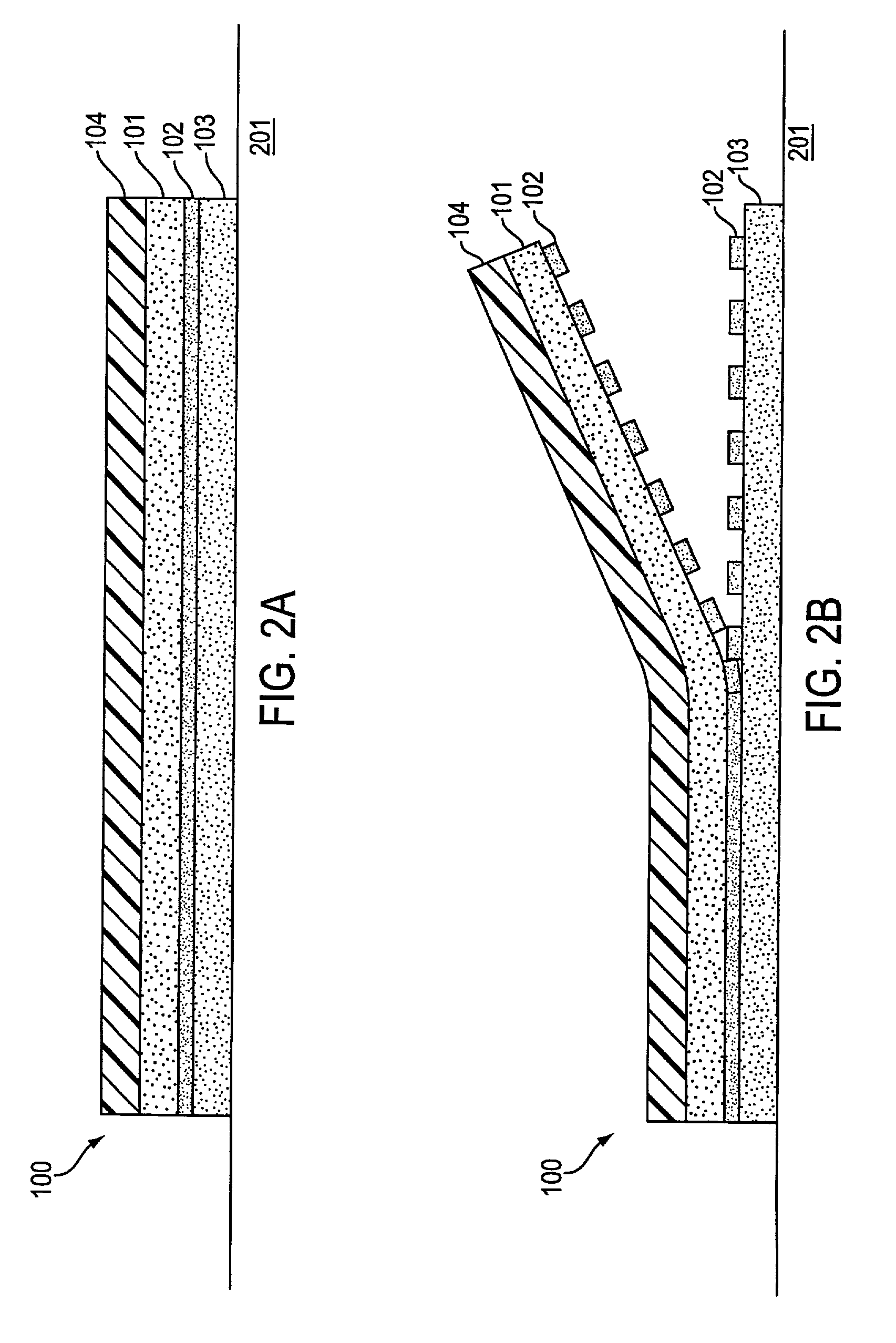
[0006]A tamper indicating label is provided. The label may comprise RFID components and a tamper track connected to the RFID components. The tamper track is preferably formed by destructible electronics. The tamper track may be modified when the label is tampered with. In one embodiment, the RFID components are able to detect the modification in the tamper track while maintaining their RFID capability. Detection of the modification in the tamper track indicates tampering of the label. In an alternative embodiment, the modification in the tamper track disables the RFID function.

Problems solved by technology

A disadvantage of current pressure sensitive label technology is that it does not allow the remote determination of whether or not a label has been tampered with or removed and relocated.

Method used


Image

  • Materials and construction for a tamper indicating radio frequency identification label
  • Materials and construction for a tamper indicating radio frequency identification label
  • Materials and construction for a tamper indicating radio frequency identification label

Examples


example 1

Manufacture of the Coating

[0147]A coating was prepared using the following ingredients.

[0148]

TABLE 2Approx.ComponentWeight %Resin25.4Phenoxy Resin (Paphen ® PKHC)Diluent74.1(Di(ethylene glycol) ethyl ether acetate)Defoamer 0.1(BYK ® 075)Colorant 0.4(Phthalocyanine Blue 12% dispersion)Polytrend ® 850-7240

[0149]The phenoxy resin is dissolved in the solvent with stirring and heating to 50–60° C. The mixture is cooled to 25° C. and the defoamer and colorant added. The solution is further mixed to combine the ingredients.

example 2

Application of the Coating

[0150]The coating of example 1 was applied to 0.05 mm thick untreated polyethylene terephthalate film through a patterned 300 mesh stainless steel screen using standard screen printing technology.

[0151]The screen mesh was selected to produce a dry ink film thickness (DIFT) of between 3 and 7 microns, 4–5 microns being the typical DIFT. Stainless steel or polymer mesh screens are acceptable. The applied coating was cured in a conveyor oven at 120° C. for 60 seconds.

[0152]Alternatively, in the case of a radiation cured formula a subtractive technique can be used. These formulas are commonly referred to as photo imagable wherein the coating is applied as a solid continuous layer. This layer is then exposed to the radiation through a mask or phototool containing the desired pattern. The areas of the coating where the radiation is not blocked by the mask are cured and remain intact. The areas of the coating where the radiation is blocked remain uncured and are s...


PUM


Abstract

Materials and construction for a tamper indicating radio frequency identification (RFID) label are provided to permit the destruction of the label or its properties in the event of attempts to remove the label from a surface to which it has been applied. An adhesion modifying coating is applied to a label surface or portions thereof to affect the relative adhesion strengths between different layers or areas of the label. The adhesion modifying coating can be applied in selected patterns to achieve differential adhesion strengths and resulting differential separation of the label from a surface on which it has been applied.

Description

CROSS REFERENCE TO RELATED APPLICATIONS[0001]This application claims priority under 35 U.S.C. §119(e) to provisional application Ser. No. 60 / 221,640 filed Jul. 28, 2000 and application Ser. No. 60 / 236,218 filed Sep. 28, 2000.STATEMENT REGARDING FEDERALLY SPONSORED RESEARCH OR DEVELOPMENT[0002]N / ABACKGROUND OF THE INVENTION[0003]Radio Frequency Identification (RFID) is being used increasingly as a means to identify goods at a distance, without requiring physical contact or even line of sight access to the goods. RFID enables information about an item to be stored on an item and in some implementations also allows this stored information to be modified at a distance. The most compact and cost effective means to provide this RFID capability is by means of a pressure sensitive (i.e. self-adhesive) label incorporating an RFID capability.[0004]The ability to detect remotely whether a pressure sensitive label or seal applied to an item has been tampered with or removed is becoming increasi...

Claims


Application Information

Patent Timeline
Patent Type & Authority Patents(United States)
IPC IPC(8): G08B13/14G06K19/073G08B13/24
CPCG06K19/073G06K19/0739G08B13/2414G08B13/2442G08B13/2437G08B13/244G08B13/2417
Inventor ATHERTON, PETER S.PRICE, DAVID M.WHITEFIELD, JAMESCAO, MIAO YONG
Owner MAJKOKH CORP
Learn More