Ultra-wideband planar antenna having frequency notch function

a technology of ultra-wideband and planar antenna, which is applied in the direction of antennas, slot antennas, antenna feed intermediates, etc., can solve the problems of bowtie antenna and tapered slot antenna, tem horn antenna and biconical antenna, unsuitable for small wireless communication, and limited us

Active Publication Date: 2006-05-23
SAMSUNG ELECTRONICS CO LTD
View PDF9 Cites 40 Cited by
  • Summary
  • Abstract
  • Description
  • Claims
  • Application Information

AI Technical Summary

Benefits of technology

[0011]Therefore, the present invention has been designed in view of the above and other problems, and it is an object of the present invention to provide an ultra-wideband, planar antenna, which comprises a “V”-shaped slot, thereby being capable of providing a frequency notch function.
[0012]It is another object of the present invention to provide an ultra-wideband, planar antenna, which is configured in such a fashion that a slot for providing a frequency notch function, that is adjustable in length and width thereof, thereby being capable of varying a frequency notch band.
[0013]It is yet another object of the present invention to provide an ultra-wideband, planar antenna, which has a frequency notch function for preventing interference with electromagnetic waves of existing communication systems.
[0014]It is still another object of the present invention to provide an ultra-wideband, planar antenna, which realizes a frequency notch function in a small planar antenna, thereby achieving compact portable communication equipment for ultra-wideband communication systems.
[0015]It is further another object of the present invention to provide an ultra-wideband, planar antenna, which is mass-produced using a printed circuit board method, thereby reducing manufacturing costs of communication equipment.

Problems solved by technology

Currently, wideband communication systems using electric pulses have been mainly used in military applications, and even when used in non-military applications their use has been limited to detecting mines buried under the ground or searching for survivors buried under collapsed buildings.
The TEM horn antenna and biconical antenna, however, are unsuitable for use in small wireless communication ultra-wideband systems since they are relatively large, and have a three-dimensional design.
The bowtie antenna and tapered slot antenna, which are both small in size, have difficulty satisfying impedance characteristics throughout a required wideband of the wireless communication ultra-wideband systems.

Method used


Image

  • Ultra-wideband planar antenna having frequency notch function
  • Ultra-wideband planar antenna having frequency notch function
  • Ultra-wideband planar antenna having frequency notch function

Examples


Embodiment Construction

[0027]An ultra-wideband antenna in accordance with preferred embodiments of the present invention will be described in detail herein below with reference to the annexed drawings. In the following description, a detailed description of known functions and configurations incorporated herein will be omitted when it may make the subject matter of the present invention rather unclear. Also, the terms used in the following description are terms defined by considering the functions obtained in accordance with the present invention.

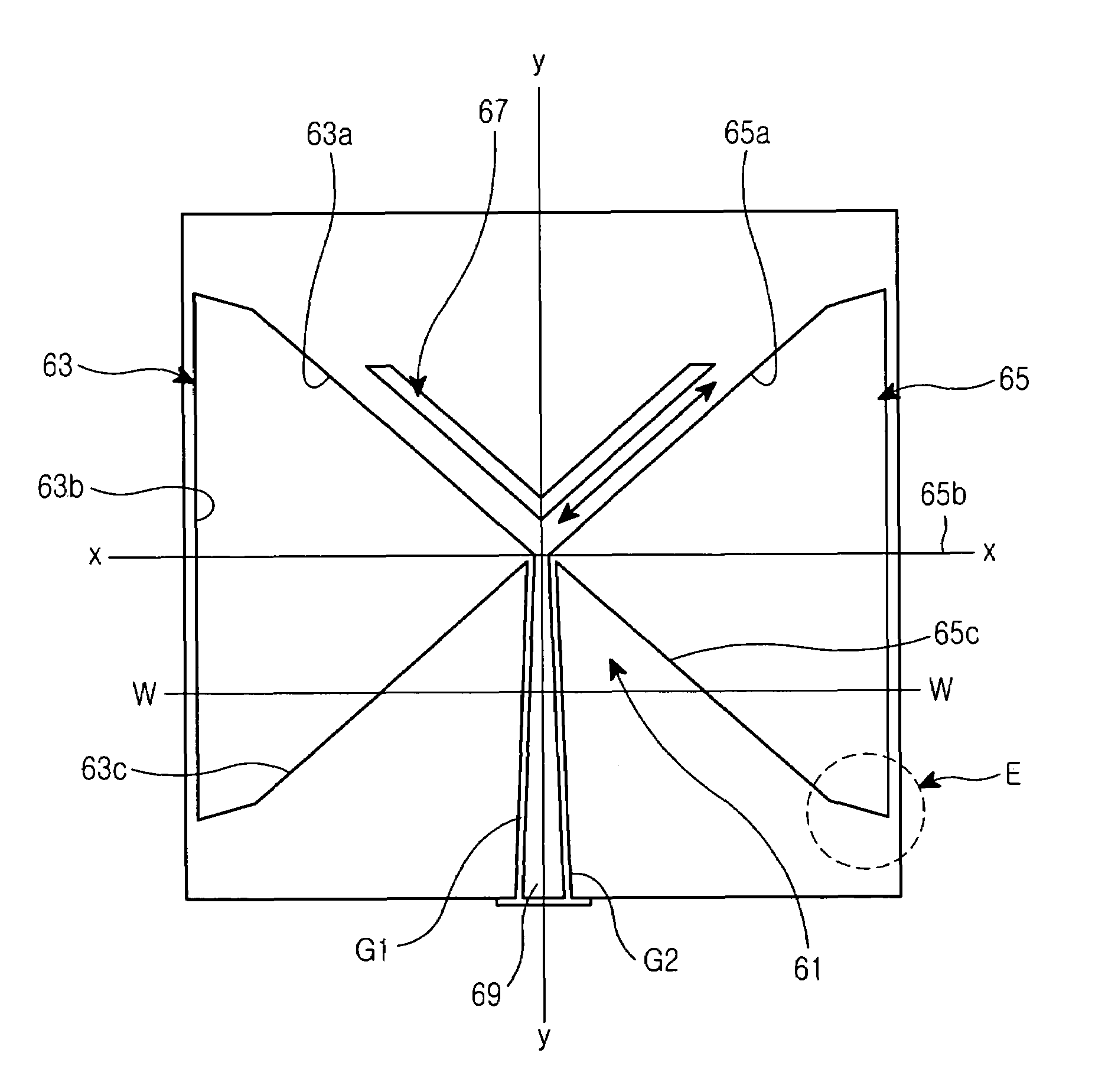
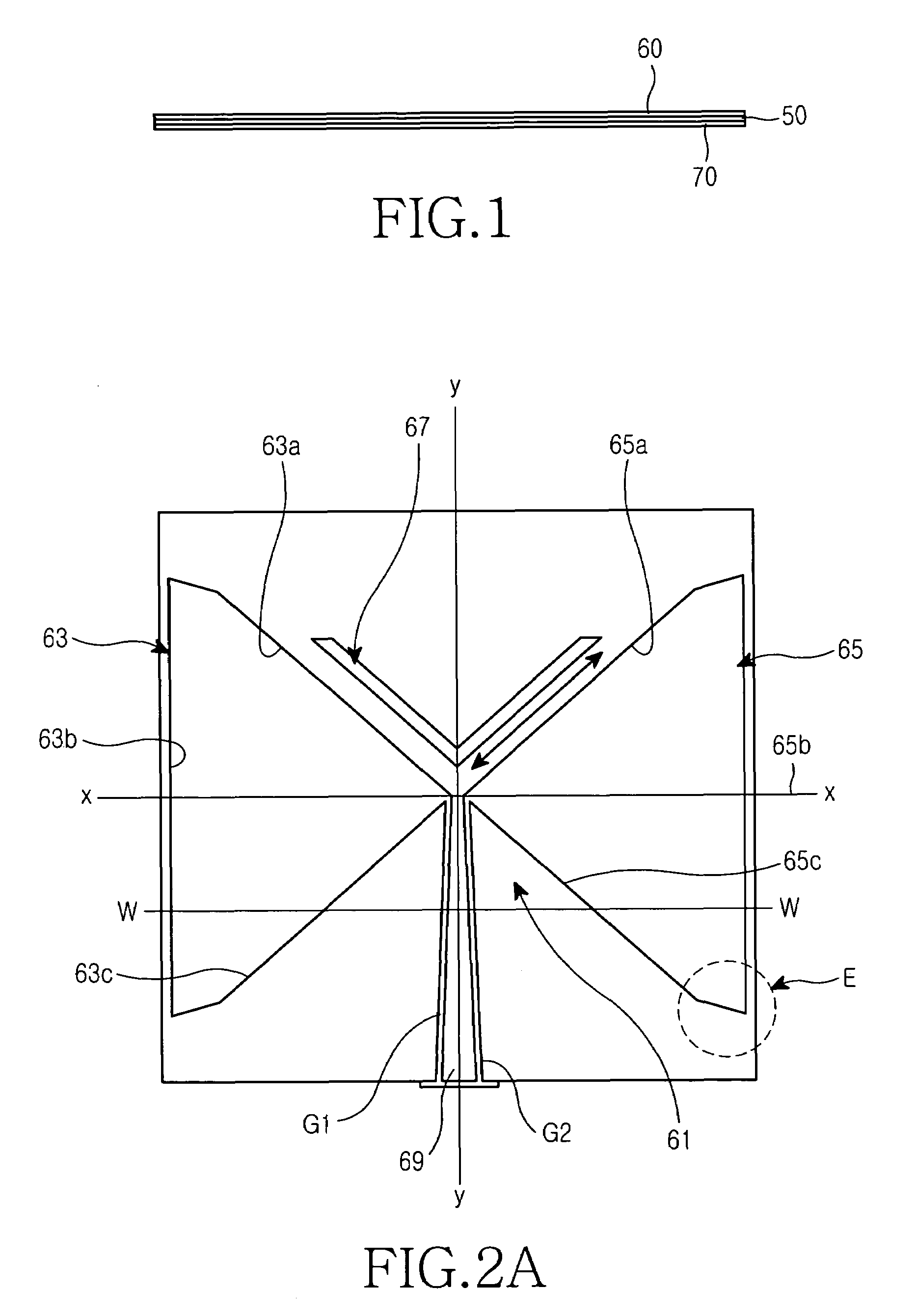
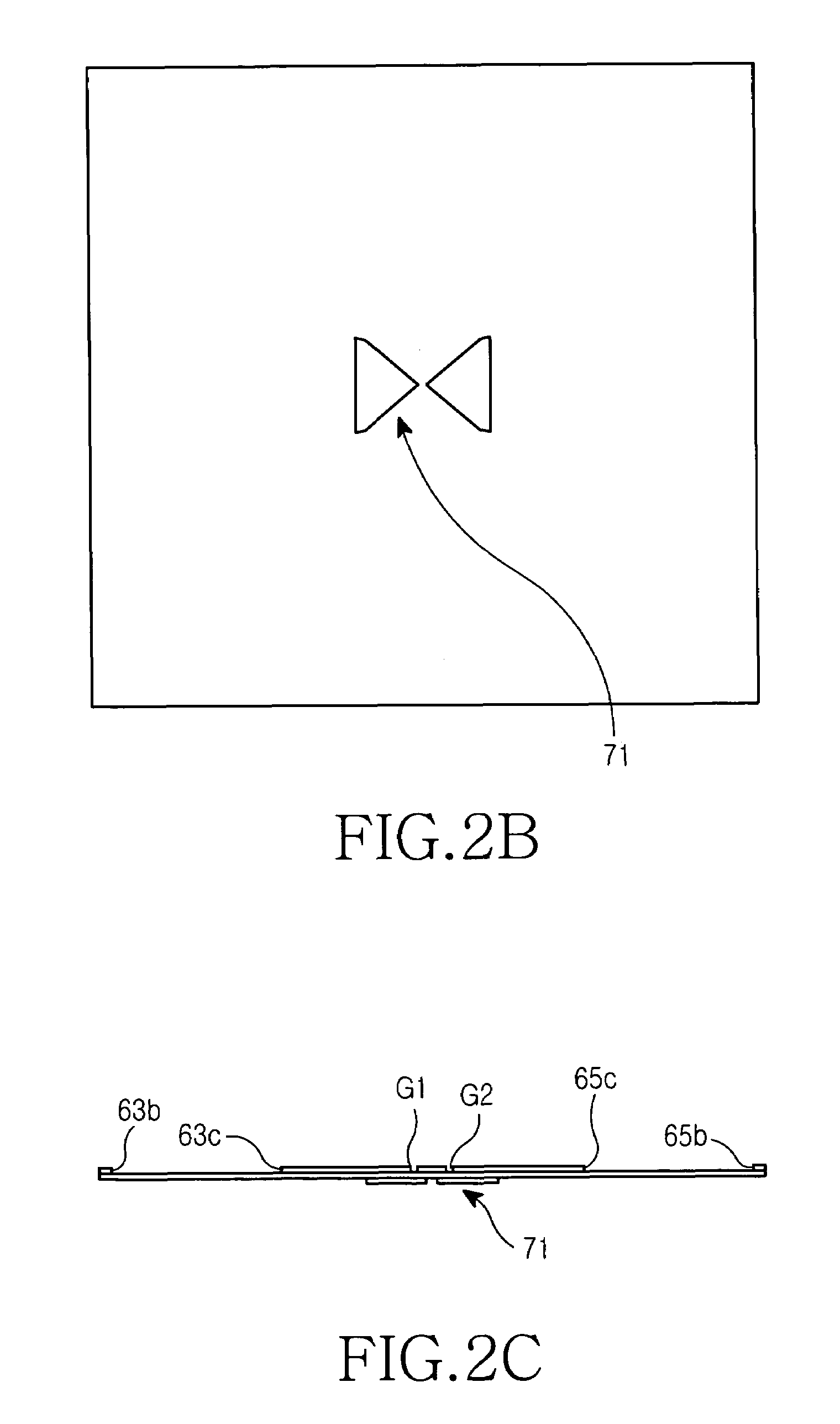
[0028]In accordance with preferred embodiments of the present invention, an ultra-wideband antenna is configured in such a fashion that an antenna radiator is made of a thin metal plate 3 cm in length and 3 cm in width. The material of the antenna radiator is removed to form a bowtie shaped slot. The metal plate is stacked on one surface of a dielectric substrate.

[0029]In addition, in order to improve the impedance characteristics of the antenna in a required wid...


PUM


Abstract

A planar antenna manufactured by patterning a substrate consisting of a dielectric layer, and first and second conductive layers applied, respectively, to both opposite surfaces of the dielectric layer. A first slot is formed in the first conductive layer for radiating electric waves. A second slot is formed in the first conductive layer for intercepting a particular frequency of the electric waves radiated by the first slot. A power supply portion is formed with the first conductive layer for supplying electric current to the first slot. A radiating element formed with the second conductive layer, which is excited by the electric waves radiated by the first slot, and radiates the electric waves.

Description

PRIORITY[0001]This application claims priority to an application entitled “ULTRA-WIDEBAND PLANAR ANTENNA HAVING FREQUENCY NOTCH FUNCTION”, filed in the Korean Intellectual Property Office on Dec. 31, 2003 and assigned Serial No. 2003-101708, the contents of which are hereby incorporated by reference.BACKGROUND OF THE INVENTION[0002]1. Field of the Invention[0003]The present invention relates generally to a wireless communication system, and more particularly to a planar antenna for use in an ultra-wideband wireless communication system having a frequency notch function.[0004]2. Description of the Related Art[0005]Currently, wideband communication systems using electric pulses have been mainly used in military applications, and even when used in non-military applications their use has been limited to detecting mines buried under the ground or searching for survivors buried under collapsed buildings. However, according to an approval given in 2002 by the Federal Communications Commiss...

Claims


Application Information

Patent Timeline
Patent Type & Authority Patents(United States)
IPC IPC(8): H01Q13/10H01Q13/08H01Q1/38
CPCH01Q13/106H01Q13/10H01Q13/08
Inventor KIM, YONG-JINKWON, DO-HOONLEE, SEONG-SOO
Owner SAMSUNG ELECTRONICS CO LTD
Why Eureka
Try Eureka