
3D image/2D image switching display apparatus and portable terminal device

Active Publication Date: 2006-05-23
VISTA PEAK VENTURES LLC
View PDF13 Cites 66 Cited by
  • Summary
  • Abstract
  • Description
  • Claims
  • Application Information

AI Technical Summary

Benefits of technology

[0013]Accordingly, it is an object of the invention to provide a thin, small and low-cost 3D image / 2D image switching display apparatus which ensures fast switching between the display of a 3D image and the display of a 2D image, provides a high display quality and is particularly suitable for mobile usages such as in a portable telephone and PDA (Personal Digital Assistant), and a portable terminal device which uses this 3D image / 2D image switching display apparatus.

Problems solved by technology

With the use of the glasses-using type which includes an anaglyph type and a polarization glass type using polarization, a user cannot substantially avoid wearing glasses.
This particularly raises a significantly problem that the visibility of texts characters which are used most frequently at the time of displaying a 2D image drops significantly.
The prior art however has the following problems.
As switching means to switch between enabling and disabling of the lens effect of the lenticular lens is large in scale, the 3D image / 2D image switching display apparatus disadvantageously becomes thicker and larger.
The existence of the switching means reduces the display quality.
Further, the operation of the switching means takes times, resulting in a longer time needed to switch between the display of a 3D image and the display of a 2D image.
Furthermore, the provision of the switching means increases the cost for the 3D image / 2D image switching display apparatus.
The requirements inevitably enlarge the apparatus and increase the cost.
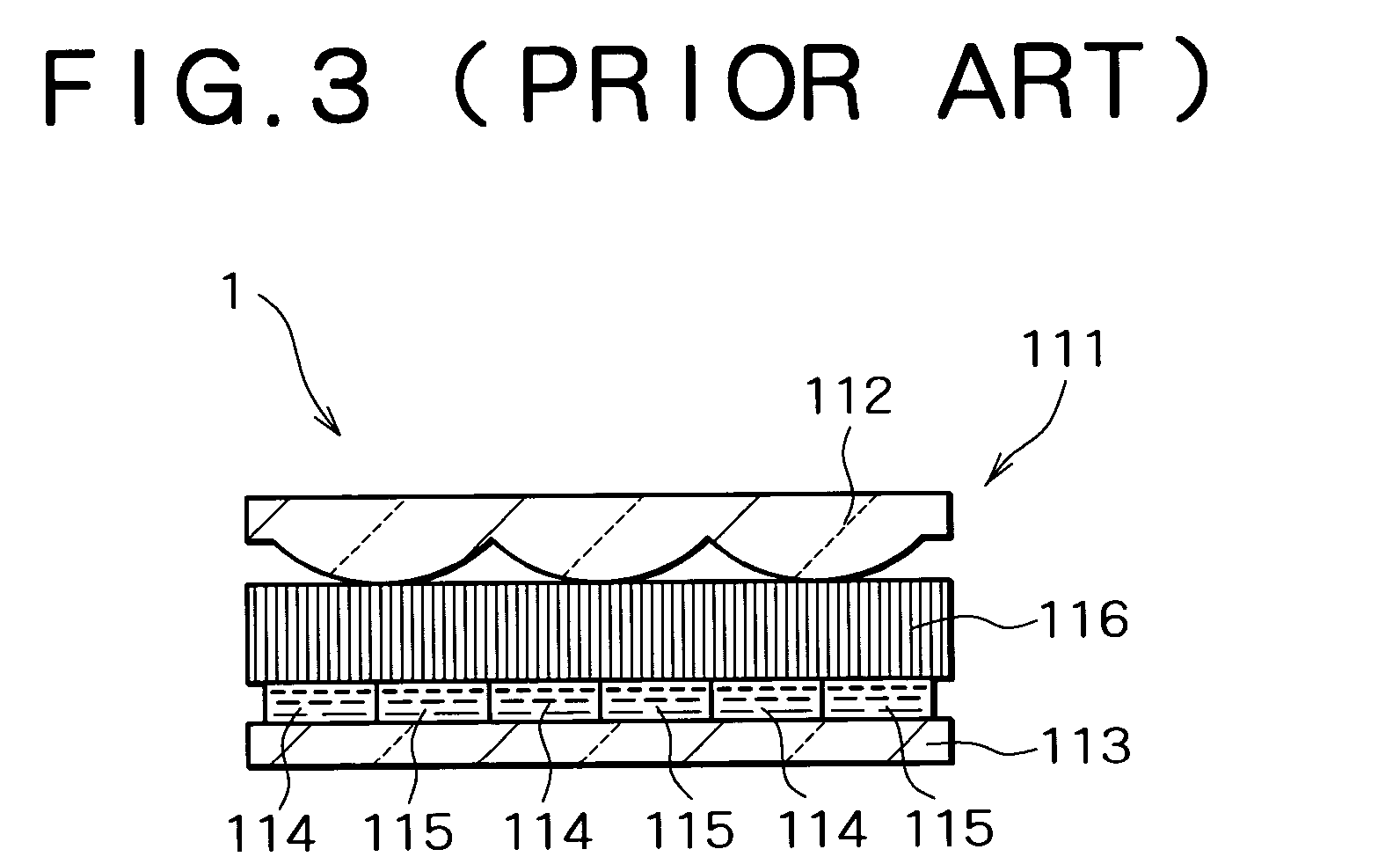
If the injection and discharge of the liquid substance are not done completely, bubbles or the like are produced, thereby reducing the display quality.
In addition, the injection and discharge of the liquid substance take time, resulting in a longer time to switch the display of 2D and 3D images from one to another.
This structure needs space for changing the distance and thus increases the thickness of the 3D image / 2D image switching display apparatus.
The need to use the expensive fiber face plate 116 or the like leads to a cost increase.
There is another problem that the movement of the lenticular lens 112 takes time.

Method used


Image

  • 3D image/2D image switching display apparatus and portable terminal device
  • 3D image/2D image switching display apparatus and portable terminal device
  • 3D image/2D image switching display apparatus and portable terminal device

Examples


first embodiment

[0079]Embodiments of the invention will be described specifically below with reference to the accompanying drawings. First, the first embodiment will be described. FIG. 4 is a cross-sectional view showing a 3D image / 2D image switching display apparatus according to the embodiment and FIG. 5 is a perspective view showing a portable terminal device according to the embodiment. FIG. 4 also shows a right eye 51 and a left eye 52 of an observer.

[0080]As shown in FIG. 4, the 3D image / 2D image switching display apparatus 1 according to the embodiment (hereinafter simply called “switching display apparatus 1” too) is provided with a liquid crystal display (LCD) unit 2 with an optical distributor 3 provided on that side of the LCD unit 2 from which light is output.

[0081]The LCD unit 2 is provided with a backlight 10 and a glass substrate 23, a liquid crystal (LC) layer 24, a color filter 26 and a glass substrate 25 are provided at that position of the LCD unit 2 where light from the backligh...

second embodiment

[0139]the invention will be described below. FIG. 16 is a cross-sectional view showing a 3D image / 2D image switching display apparatus according to the embodiment, and shows a 2D-image display state. FIG. 17 is a graph showing the results of the simulation on the apparatus shown in FIG. 16, with the observation position taken on the horizontal axis and the irradiance at the observation position taken on the vertical axis. The embodiment is characterized in that the positions of the lenticular lenses at the time of displaying a 2D image are shifted by a quarter (¼) of the lens pitch, with respect to the pixels of the display unit, from the positions taken at the time of displaying a 3D image.

[0140]According to the first embodiment, because the non-display area of a pixel is magnified too at the time of displaying a 2D image as shown in FIG. 10, a non-2D visible range where a 2D image cannot be identified is produced in the 2D visible range. As this non-2D visible range overlaps a 3D ...

fifth embodiment

[0159]the invention will be described next. FIGS. 21A and 21B are cross-sectional views showing a 3D image / 2D image switching display apparatus according to the embodiment of the invention. FIG. 21A shows a 2D-image display state and FIG. 21B shows a 3D-image display state. FIG. 22 is a graph showing the shape of a lens with the position on the lens perpendicular to the optical axis taken on the horizontal axis and the height of the lens at the position taken on the vertical axis. FIG. 23 is a diagram showing the path of light output from one end portion of one pixel, FIG. 24 is a diagram showing the path of light output from the other end portion of this pixel, and FIG. 25 is a diagram showing the path of light output from the center portion of the pixel. Further, FIG. 26 is a graph showing the results of the simulation on the apparatus shown in FIGS. 21A and 21B, with the observation position taken on the horizontal axis and the irradiance at the observation position taken on the ...


PUM


Abstract

A 3D image / 2D image switching display apparatus is provided with a liquid crystal display unit and first and second lenticular lenses. To display a 3D image, the first lenticular lens is arranged in such a way that the optical axis of the first lenticular lens coincides with the optical axis of the second lenticular lens so that pixels for a left eye display an image for a left eye and pixels for a right eye display an image for a right eye. To display a 2D image, the first lenticular lens is arranged in such a way that the optical axis of the first lenticular lens is shifted from the optical axis of the second lenticular lens by half a lens pitch so that the pixels for the left eye and the pixels for the right eye display the same image independently.

Description

BACKGROUND OF THE INVENTION[0001]1. Field of the Invention[0002]The present invention relates to a three-dimensional (3D) image / two-dimensional (2D) image switching display apparatus which can display a 3D image and a 2D image, switching them from one to the other, and a portable terminal device incorporating the 3D image / 2D image switching display apparatus.[0003]2. Description of the Related Art[0004]Display apparatuses capable of displaying 3D images have been developed. 3D image display systems that have been studied so far can be classified into a type which uses glasses and a type which does not. With the use of the glasses-using type which includes an anaglyph type and a polarization glass type using polarization, a user cannot substantially avoid wearing glasses. In this respect, recently active studies have been made on glass-less 3D image display apparatuses which do not use glasses.[0005]Glass-less 3D image display apparatuses include a parallax barrier type and a lenticu...

Claims


Application Information

Patent Timeline
IPC IPC(8): G09G5/00G02B26/08G02B3/06G02B30/27G02F1/13G02F1/1335G03B35/18H04N13/00H04N13/04
CPCG02B3/005G02B3/0062G02B27/2214H04N13/0454H04N13/0404H04N13/045G02B27/2242H04N13/305H04N13/354H04N13/359G02B30/36G02B30/27
Inventor UEHARA, SHIN-ICHITAKANASHI, NOBUAKIHAYAMA, HIROSHI
Owner VISTA PEAK VENTURES LLC
Features
  • Generate Ideas
  • Intellectual Property
  • Life Sciences
  • Materials
  • Tech Scout
  • Unparalleled Data Quality
  • Higher Quality Content
  • 60% Fewer Hallucinations
Learn More