Optical apparatus

Active Publication Date: 2006-05-23
PROXIMITY SENSORS OF TEXAS LLC
View PDF4 Cites 40 Cited by
  • Summary
  • Abstract
  • Description
  • Claims
  • Application Information

AI Technical Summary

Benefits of technology

[0011]An object of the invention is to provide an impact optical a

Problems solved by technology

As the demand increases for functions, mobility and small size of the optical apparatuses, it becomes a challenge to product such apparatuses with impact size, high accuracy, simple assembling processes and low cost of assembling.
As the number of functions and components increase, however, the optical apparatus package inevitably trends toward integration and modulization to save space.
With respect to

Method used


Image

  • Optical apparatus
  • Optical apparatus
  • Optical apparatus

Examples


Example

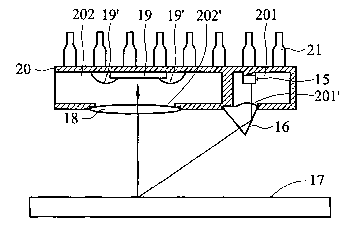
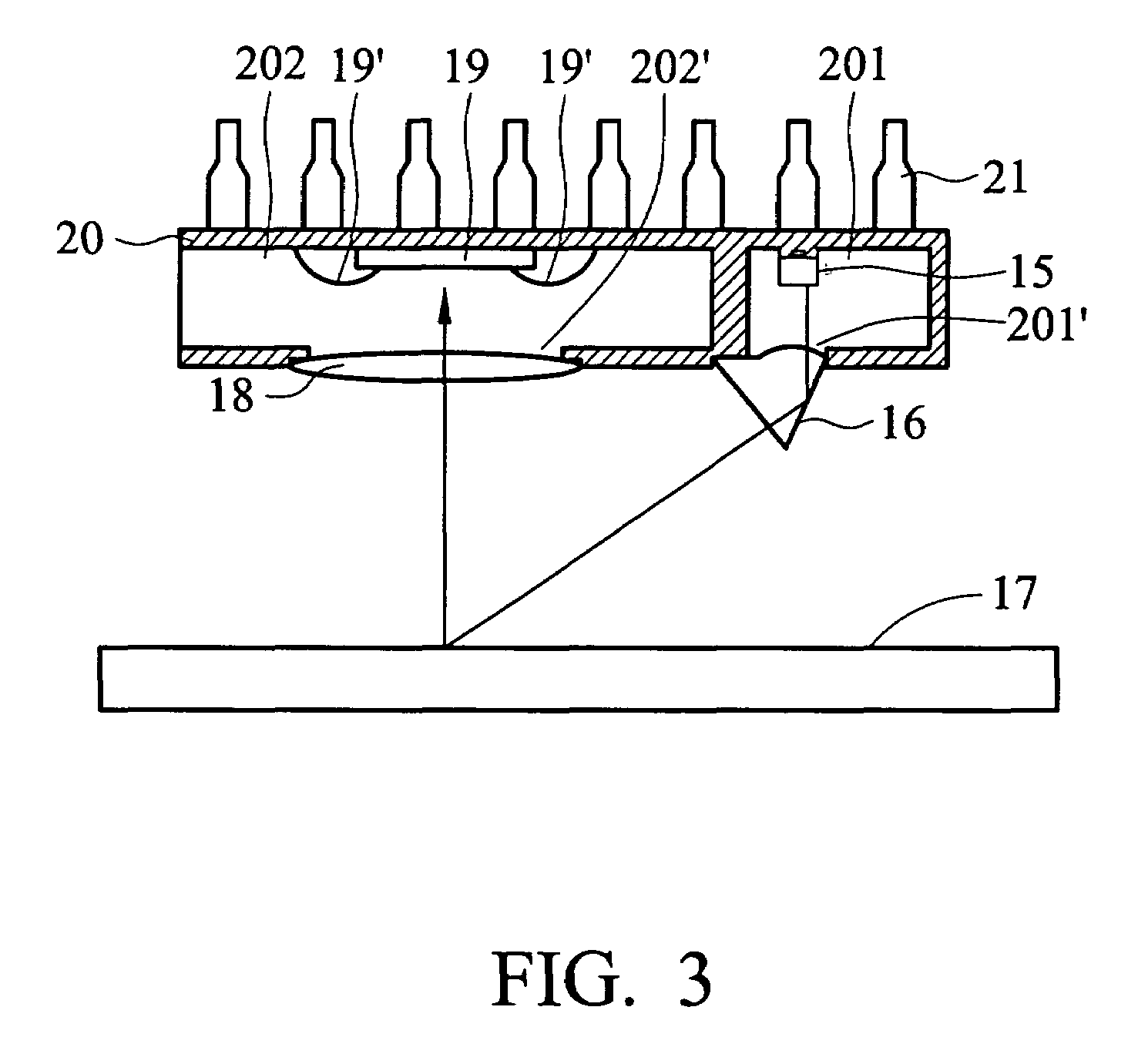
[0020]FIG. 3 is a sectional view of the first embodiment in accordance with the present invention. As shown in FIG. 3, the optical apparatus for an object surface 17 is provided with a light emitting diode (LED) 15, a light guiding element 16, a lens 18, a sensor chip 19 and a frame 20. Particularly, the frame 20 is the traditional lead-frame type IC package structure comprising a first compartment 201 and a second compartment 202, wherein the first compartment 201 has an opening 201′ and the second compartment 202 has an opening 202′. The light emitting diode (LED) 15 is a bare LED chip mounted in the first compartment 201 by Surface Mount Technology (SMT). In FIG. 3, the light guiding element 16 is disposed in the opening 201′ and the lens 18 is disposed the opening 202′, wherein the sensor chip 19 is mounted in the second compartment 202.

[0021]As the arrow shows in FIG. 3, light emitted from the light emitting diode (LED) 15 passes through the light guiding element 16 and project...

Example

Second Embodiment

[0024]FIG. 5 is a sectional view of the second embodiment in accordance with the present invention. As shown in FIG. 5, the optical apparatus for an object surface 24 is provided with a light emitting diode (LED) 22, a light guiding element 23, a lens 25, a fixing mechanism 26, a sensor chip 27 and a frame 28. Particularly, the frame 28 is the traditional lead-frame type IC package structure comprising a first compartment 281 and a second compartment 282, wherein the first compartment 281 has openings 22′ and 281′ while the second compartment 282 has an opening 282′.

[0025]A sensor chip 27 is mounted in the second compartment 282 such that the light signal received by the sensor chip 27 is transformed into electrical signal passing through the conducting wires 27′ and the pins 29. The sensor chip 27 can electrically communicate with an external circuit or a computer through the conducting wires 27′ and the pins 29.

[0026]In this embodiment, the light emitting diode (L...


PUM


Abstract

An optical apparatus. The optical apparatus is applied to an object surface, comprising a frame, a light emitting device and an optical sensor. The frame is disposed in the optical apparatus, having a first compartment and a second compartment, wherein the first compartment has a first opening and the second compartment has a second opening. The light emitting device is disposed in the first compartment, wherein light emitted from the light emitting device passes through the first opening and is reflected by the object surface outside the frame. The optical sensor is disposed in the second compartment to receive light reflected from the object surface passing through the second opening.

Description

BACKGROUND OF THE INVENTION[0001]1. Field of the Invention[0002]The present invention relates to an optical apparatus, and in particular to a compact optical apparatus for use on an object surface with limited area, that offers high accuracy and low assembly cost.[0003]2. Description of the Related Art[0004]Applications relative to optical interface technology, such as optical pointing devices, have become increasingly popular. For example, conventional and optical pointing devices and optical pens are successful applications of apparatuses employing optical sensor technology. As the demand increases for functions, mobility and small size of the optical apparatuses, it becomes a challenge to product such apparatuses with impact size, high accuracy, simple assembling processes and low cost of assembling.[0005]With respect to the conventional optical pointing devices and optical pens, mobility increases with reduced size such that they are more convenient, particularly for use with mo...

Claims


Application Information

Patent Timeline
IPC IPC(8): G09G5/08G06F3/03G06F3/033
CPCG06F3/03545G06F3/0317
Inventor HUANG, CHIEN-CHANGLIN, CHUN-HUANGLAN, JENG-FENG
Owner PROXIMITY SENSORS OF TEXAS LLC
Why Eureka
Try Eureka