Arbitrary object tracking augmented reality applications

a technology of augmented reality and tracking objects, applied in the direction of direction/deviation determining electromagnetic systems, instruments, static indicating devices, etc., can solve the problems of large amount of computer processing power, cost, and high cost of ar systems

Active Publication Date: 2006-05-23
ACCENTURE GLOBAL SERVICES LTD
View PDF23 Cites 143 Cited by
  • Summary
  • Abstract
  • Description
  • Claims
  • Application Information

AI Technical Summary

Benefits of technology

[0010]By way of introduction only, an advantage of the present invention is achieved by an apparatus and method for tracking arbitrary objects in an augmented reality (“AR”) application. The present invention improves upon conventional AR systems by providing for the selection of an arbitrary object depicted in a video image of a scene of a real-world environment and registering a computer-generated image to the selected object, such that the computer-generated image accurately tracks the video image of the selected real-world object as the user's view of the environment changes or as the object moves.
[0011]It is a goal of the present invention to track arbitrary objects in augmented reality applications without requiring remote sensing equipment, prior knowledge of the environment, or objects in the environment.
[0012]It is another goal of the present invention to track a selected real-world object with a computer-generated image without pre-programmed information related to the placement, arrangement, position, orientation, or relationships of objects or the real-world environment. A computer-generated image may be embedded in a video image or within the user's field of view so as to accurately track the selected real-world object as the object and / or field of view of the user changes.
[0013]It is another goal of the present invention to track an arbitrary object in a real-world environment with a computer-generated image based on a calculation of a center of mass, or centroid, of an interframe difference of video images of the arbitrary object.
[0014]It is another goal of the present invention to track an arbitrary object in a real-world environment with a computer-generated image based on repetitive a determination of interframe differences for consecutive sequential video frames and calculations of the centroid for each sequential interframe difference. A virtual image may be located in a user's field of view or in the video image according to the centroid of for each sequential interframe difference. The video image with the virtual image may be displayed to the user and at a remote terminal.
[0015]One or more of the above goals and other goals may be achieved by an AR system having a video capturing device; a processor configured to generate and register a computer-generated virtual image to a selected object depicted in a video image according to a centroid of an interframe video image difference.

Problems solved by technology

Such systems, however, may require a large amount of computer processing power and may require a costly tracking system worn by the user.
Such AR systems are costly and do not allow a user to track a virtual image to an arbitrary object.

Method used


Image

  • Arbitrary object tracking augmented reality applications
  • Arbitrary object tracking augmented reality applications
  • Arbitrary object tracking augmented reality applications

Examples


Embodiment Construction

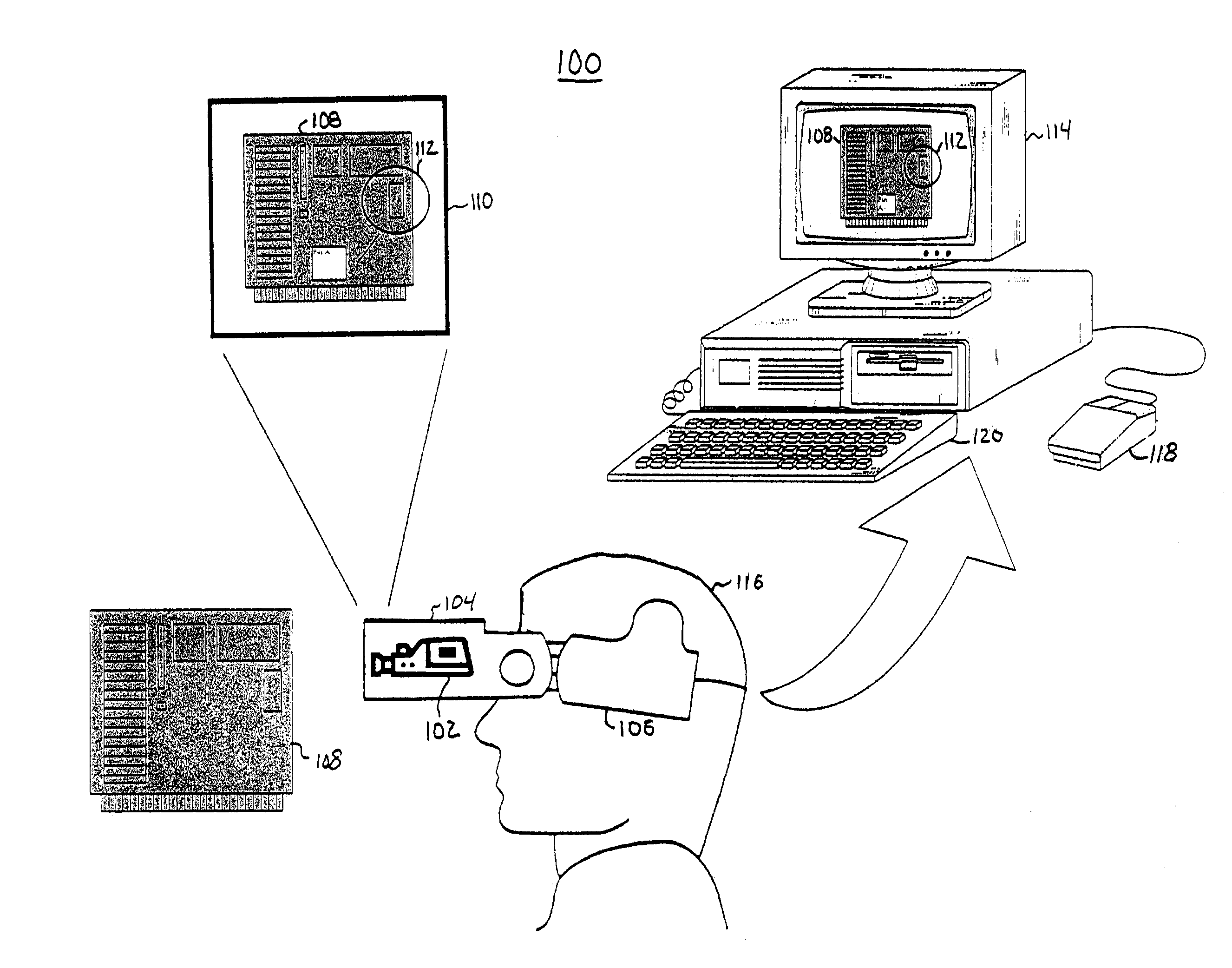
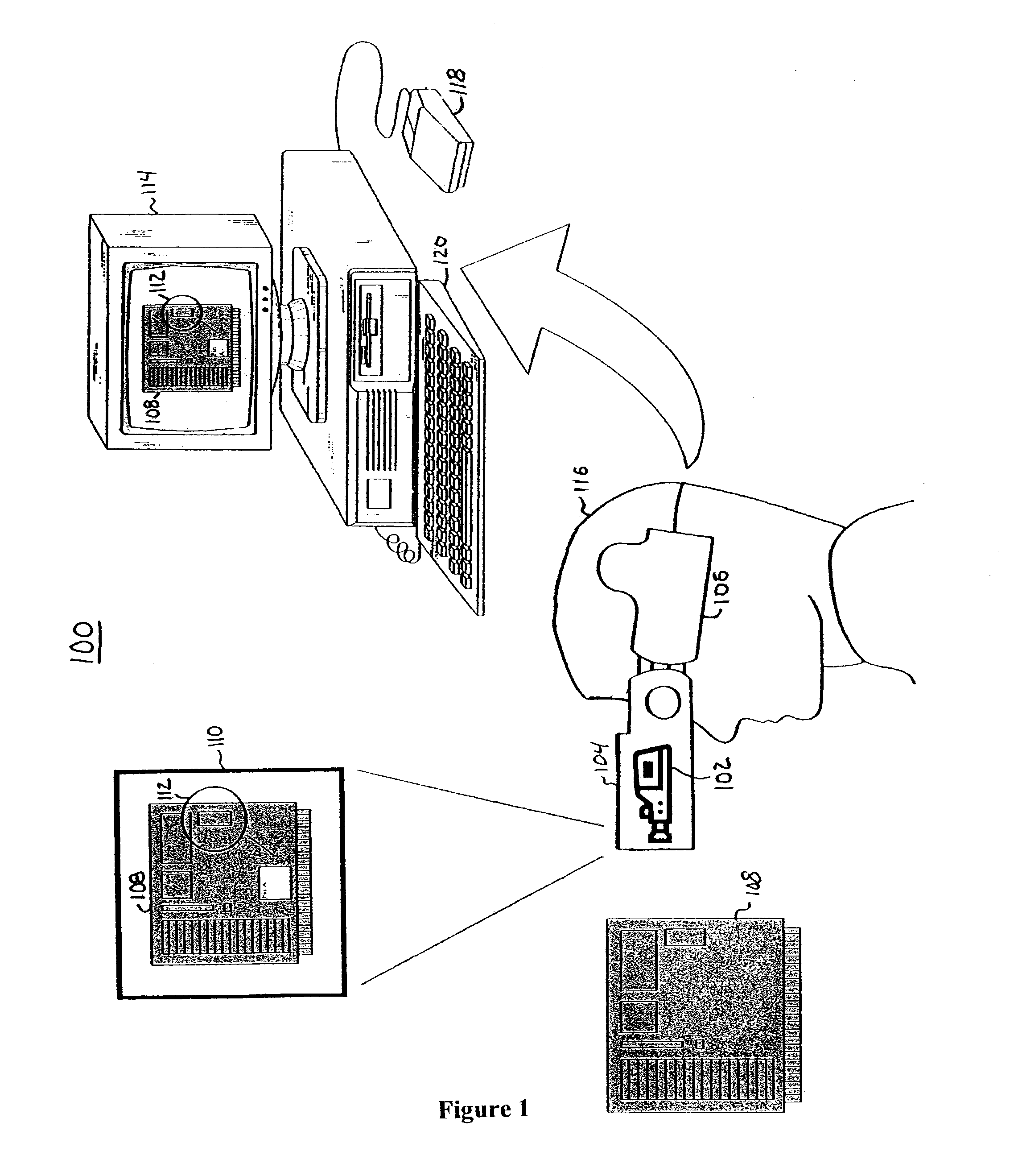
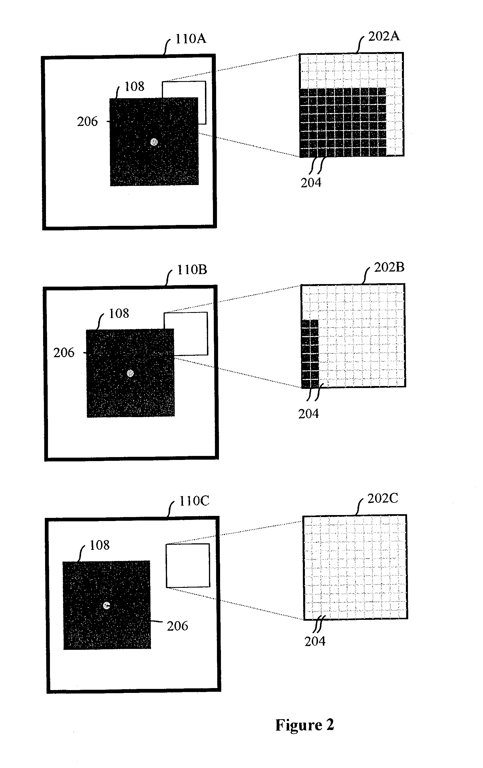
[0028]The present invention will now be described more fully with reference to the accompanying drawings. In each of the following figures, components, features and integral parts that correspond to one another each have the same reference number. The drawings of the figures are not true to scale.

[0029]The invention may be embodied in many different forms and should not be construed as limited to the embodiments set forth herein. These embodiments are described to provide a thorough and complete disclosure and fully convey the scope of the invention. The present invention may be embodied as a method, a data processing system, a software product, or an augmented reality system. The present invention may take the form of electronic hardware embodiment, a computer software embodiment, or as an embodiment of a combination of both hardware and software. Accordingly, the present invention may be embodied as electronic components, utilizing a computer program product on a computer-readable...


PUM


Abstract

Video images of objects in a real-world environment are taken from the perspective of a viewer. The user's field of view may be captured in the video images that are processed to select a segment of the video image or an object depicted in the video image. An image such as a computer-generated annotation or graphic overlay way be registered to the segment, and therefore track the segment from the user's field of view of the segment, without prior knowledge of the spatial relationship of the segment to the real-world environment according to a centroid for an interframe difference of the video image associated with the selected object. The image may be displayed in the user's field of view or in the video image. The computer-generated image tracks the movement of the segment with respect to the video image.

Description

BACKGROUND[0001]1. Field of the Invention[0002]The present invention relates generally to interactive viewing systems. In particular, the present invention relates to tracking an arbitrary object in an augmented reality viewing system.[0003]2. Description of the Related Art[0004]Interactive viewing systems have found application in manufacturing automation and maintenance, surgical procedures, educational instruction, mechanical, architectural, and interior designs, multimedia presentations, and motion picture production. Such interactive viewing systems may display computer-generated overlay images, such as a rendering of annotations, blueprints, component parts, buildings, backgrounds, and other images, in a user's field-of-view of a real-world environment to provide information about the real-world objects.[0005]One type of interactive viewing system is referred to as an augmented reality (AR) system. In an AR system, computer-generated images, or virtual images, may be embedded ...

Claims


Application Information

Patent Timeline
Patent Type & Authority Patents(United States)
IPC IPC(8): G09G5/00G01S3/786G02B27/00G02B27/01G06F3/00G06F3/01G06F3/033G06F3/042
CPCG01S3/7864G02B27/017G06F3/0304G06F3/011G02B2027/0138G02B2027/0198G02B2027/0187
Inventor DEMPSKI, KELLY L.
Owner ACCENTURE GLOBAL SERVICES LTD
Why Eureka
Try Eureka