
Targeted mobile terminal communication blocker

a mobile terminal and communication blocker technology, applied in the field of targeted mobile terminal communication blockers, can solve the problems of all cellular phones in the target area to be jammed, cellular transmission may threaten sensitive instruments, and spotters within banks cannot communicate with outside henchmen, so as to achieve the effect of reducing interference with communications

Inactive Publication Date: 2006-05-23
PCTEL INC
View PDF10 Cites 55 Cited by
  • Summary
  • Abstract
  • Description
  • Claims
  • Application Information

AI Technical Summary

Benefits of technology

[0009]An embodiment of the present invention is a system and method for selectively blocking wireless communications within a blocking zone. In accordance with this embodiment, a call origination signal is detected from a targeted mobile terminal. An appropriate blocking response that is tailored to the origination signal is determined and a blocking signal comprising the blocking response is transmitted to the targeted mobile terminal. The blocking signal is focused on a blocking zone so as to minimize interference with communications of non-targeted mobile terminals.
[0015]It is yet another aspect of the present invention to process the targeted mobile terminal transmission to determine a channel and frequency the targeted mobile terminal has dedicated for reception, thus allowing the present invention to narrow blocking activities to specific frequencies and channels.
[0017]These and other aspects of the present invention will become apparent from a review of the general and detailed descriptions that follow. An embodiment of the present invention is a method for selectively blocking communication within a blocking zone from a targeted mobile terminal to a base station. In accordance with this embodiment, a call origination signal is detected from a targeted mobile terminal. An appropriate blocking response that is tailored to the origination signal is determined and a blocking signal comprising the blocking response is transmitted to the targeted mobile terminal. The blocking signal focused on a blocking zone so as to minimize interference with communications of non-targeted mobile terminals. In an alternate embodiment, a range of probable frequencies of a response signal from the base station is determined and a blocking signal of sufficient power is transmitted at each of the probable frequencies.
[0018]Further embodiments of the present invention are designed to minimize impact to the cellular service of mobile terminals near the targeted mobile terminal (thereby reducing the size of the blocking zone). For example, in another embodiment of the present invention, the blocking signal is focused on a blocking zone by determining the location of the targeted mobile terminal and the signal strength needed to block the signal of the targeted mobile terminal. The blocking signal is then transmitted at the blocking signal strength.
[0019]In another embodiment, the blocking signal is transmitted from a plurality of transmitters to the call origination signal location such that the cumulative strength of the blocking signal at the call origination signal location from the plurality of transmitters is about the blocking signal strength. The signal strength of the signals from any one of the plurality of transmitters is relatively low, thereby reducing interference outside the blocking zone.
[0020]Additionally, signals from the targeted mobile terminal are blocked selectively and on an intermittent basis keyed to a time period when the present invention detects communication activity by the targeted mobile terminal. In this manner, the present invention interferes with select communications while minimizing interference to other non-targeted mobile terminals.

Problems solved by technology

Further, there are some environments were cellular transmission may threaten sensitive instruments such as in hospitals.
The literature reports that some Latin American banks routinely block cellular transmission so that spotters within banks cannot communicate to outside henchmen identifying a bank patron who has made a sizable cash withdrawal.
The overiding causes all cellular phones in the target area to be jammed.
Gainsboro, however, does not teach how such transmissions are to be jammed or provide a means for limiting the jamming transmission so as to minimize interference with non-targeted terminals.

Method used


Image

  • Targeted mobile terminal communication blocker
  • Targeted mobile terminal communication blocker
  • Targeted mobile terminal communication blocker

Examples


Embodiment Construction

[0027]An embodiment of the present invention is a system and method for selectively blocking wireless communications within a blocking zone. In accordance with this embodiment, a call origination signal is detected from a targeted mobile terminal. An appropriate blocking response is determined and a blocking signal comprising the blocking response is transmitted to the targeted mobile terminal. The blocking signal is targeted at a blocking zone so as to minimize interference with communications of non-targeted mobile terminals.

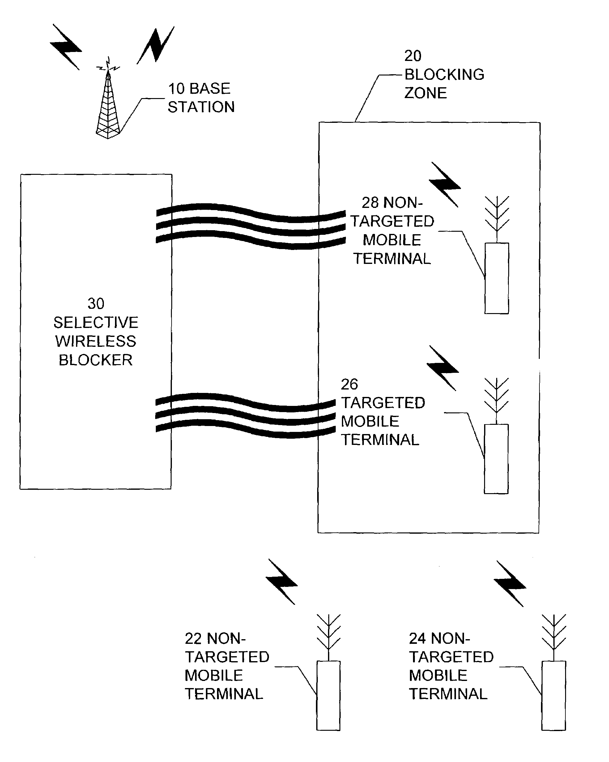
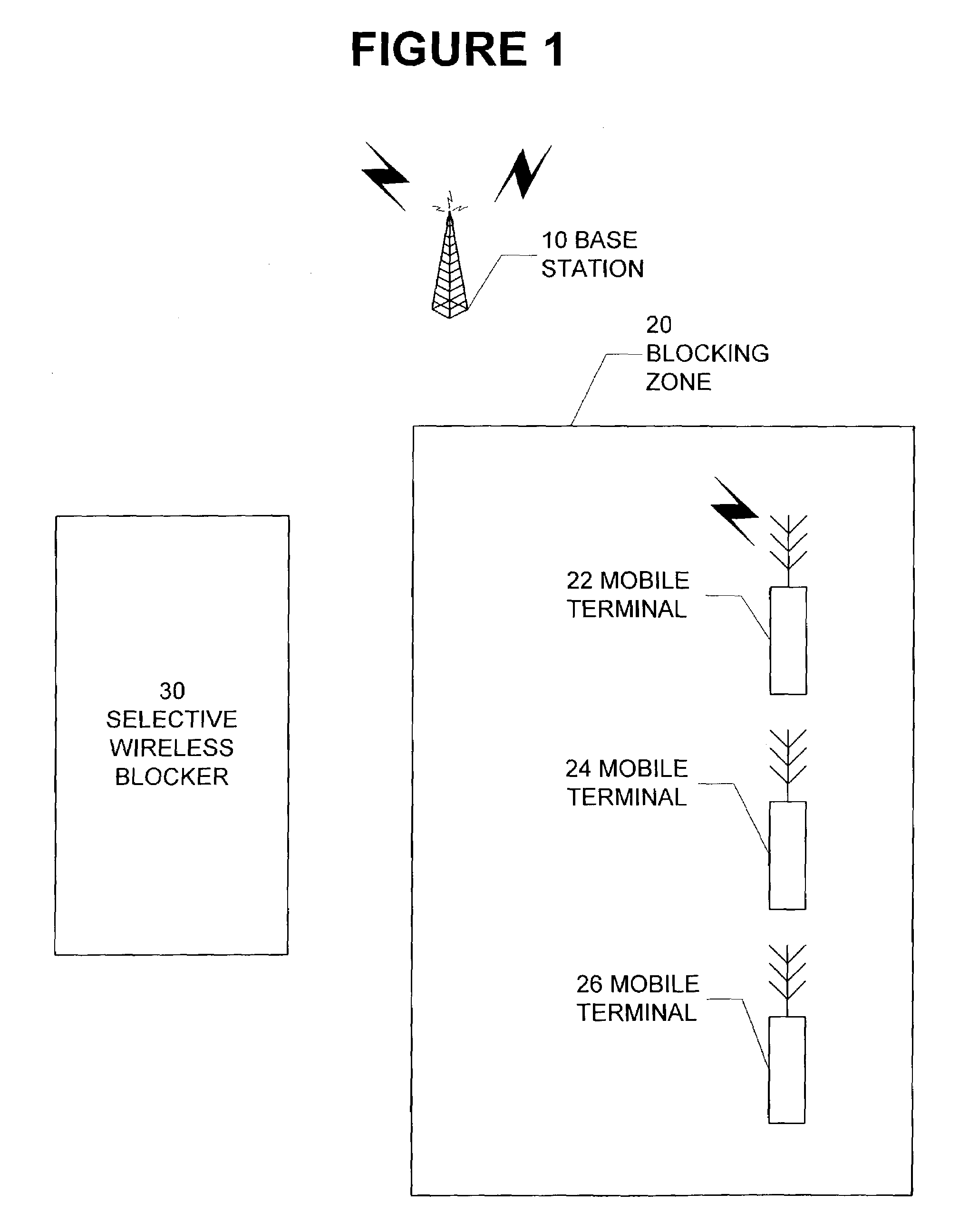
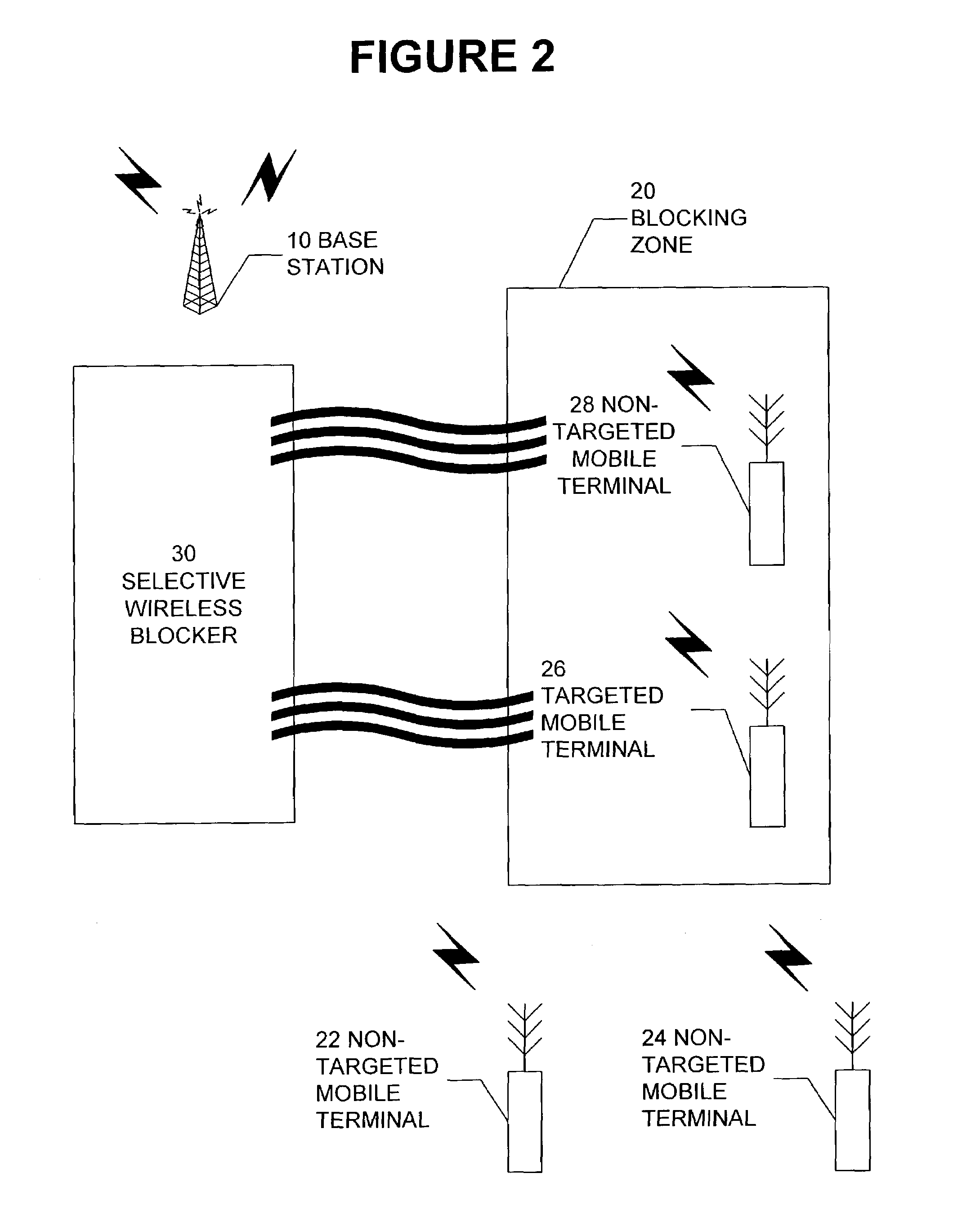
[0028]Referring to FIG. 1, three mobile terminals 22, 24 and 26 are located within a blocking zone 20. Mobile terminal 22 is engaged in wireless communication. The targeted mobile terminal 26 is quiescent as is the third terminal 24, a non-targeted mobile terminal. The selective wireless blocker 30 monitors the blocking zone for activity emanating from the targeted mobile terminal 26. A base station 10 is broadcasting multiplexed packets to clients within its ...


PUM


Abstract

A selective blocker for targeted mobile terminals. A signal monitor determines when a targeted mobile terminal is transmitting a signal to a base station. A signal analyzer identifies characteristics of the terminal signal and a processor produces a blocking response based on one or more characteristics. The blocking response is transmitted to the targeted mobile terminal to block communications between the targeted mobile terminal and the base station using the minimum power needed to effectively block the terminal signal so as to limit interference with non-targeted mobile terminals.

Description

CROSS REFERENCE TO RELATED APPLICATIONS[0001]This application claims priority under 35 U.S.C. §119(e) from provisional application No. 60 / 352,001, filed Jan. 24, 2002. The 60 / 352,001 provisional application is incorporated by reference herein, in its entirety, for all purposes.FIELD OF INVENTION[0002]This invention relates generally to wireless communication jamming. More particularly, the present invention relates to the blocking of specific wireless terminal signals within a limited area in instances where it is legal to do so or where an exception is provided for the public interest.BACKGROUND OF THE INVENTION[0003]Cellular phone blockers have been available since 1998. These blockers are used for blocking inbound and outbound cellular phone calls. There are two general methods to block a call: interfere by transmitting at the cellular frequency to be blocked; and by establishing an electronic filter to fool mobile phones that the reverse link is not being responded to, i.e., mak...

Claims


Application Information

Patent Timeline
IPC IPC(8): H04K3/00H04B7/005
CPCH04K3/43H04K3/45H04W52/50H04K3/41H04K3/42H04K2203/34H04K2203/16Y02B60/50H04K3/65H04K3/84
Inventor KLINE, PAUL A.
Owner PCTEL INC
Learn More