Method for modeling an implant and an implant manufactured by the method

Inactive Publication Date: 2006-05-23
ASAHI KOGAKU KOGYO KK +1
View PDF12 Cites 177 Cited by
  • Summary
  • Abstract
  • Description
  • Claims
  • Application Information

AI Technical Summary

Benefits of technology

[0037]This makes it possible to improv

Problems solved by technology

However, when the shape of the implant is modeled according to the above method, there are problems such as follows.
Thus, it is difficult to accurately form a model of the bone having the defect.
Therefore, there is a case that the implant that is modeled by this method has poor conformity with the shape of the defect of the bone.
In the conventional method, it may be possible to improve conformability of the model by making each plate thinner, but there is a limit in this approach, thus it is difficult to obtain satisfactory shape conformability.
Further, when the thickness of the plate is

Method used


Image

  • Method for modeling an implant and an implant manufactured by the method
  • Method for modeling an implant and an implant manufactured by the method
  • Method for modeling an implant and an implant manufactured by the method

Examples


Embodiment Construction

[0049]Hereinbelow, based on the accompanying drawings, a detailed description will be made with regard to a preferred embodiment of a method for modeling an implant and an implant manufactured by the method according to the present invention.

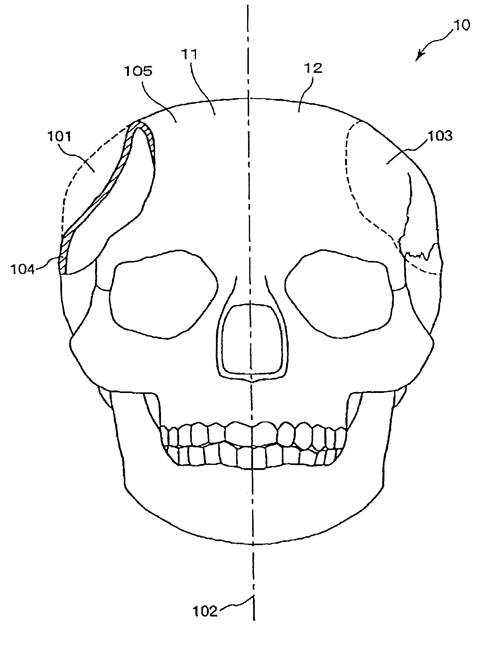
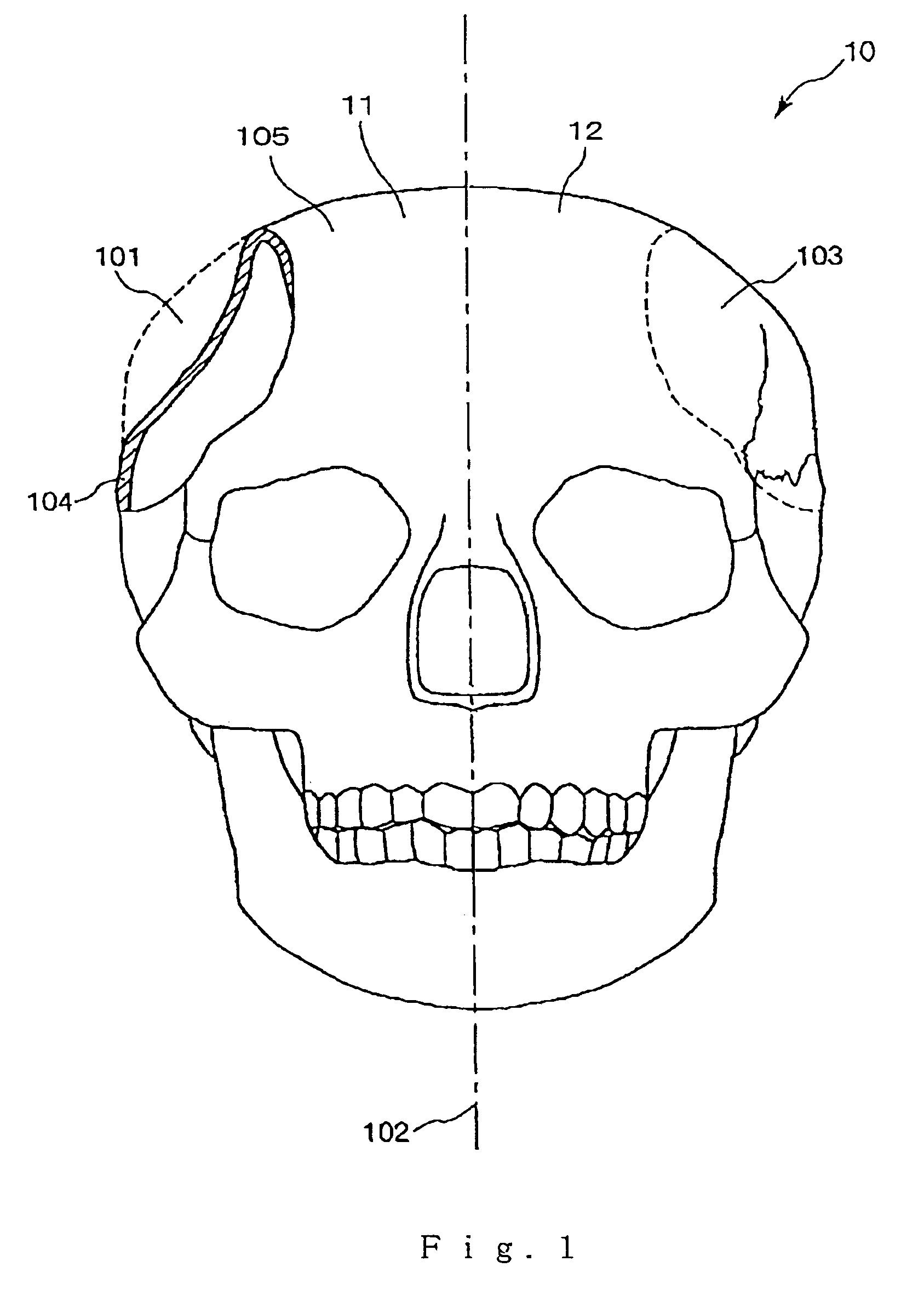
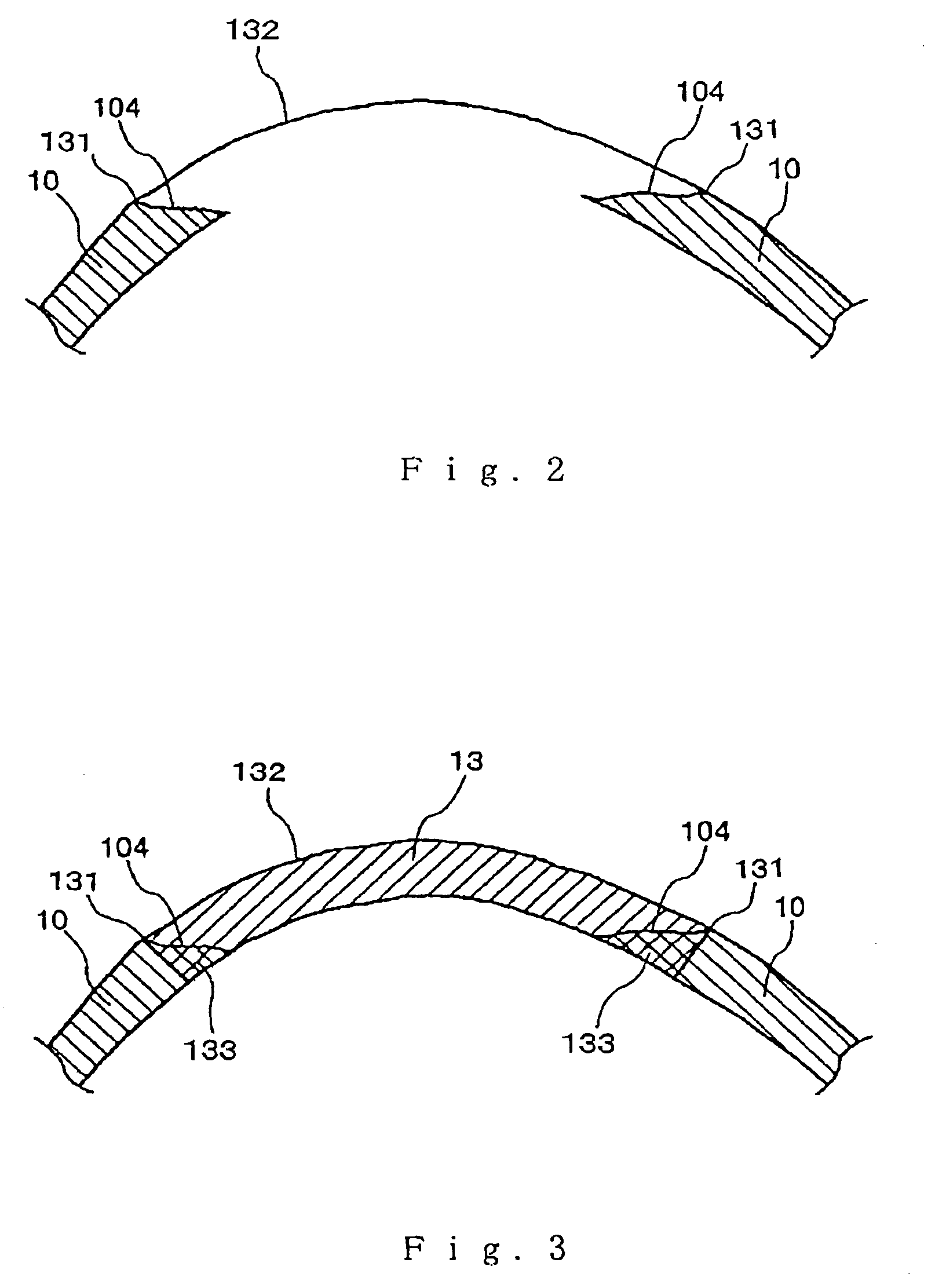
[0050]FIG. 1 is an illustration of three-dimensional data of a bone produced based on a plurality of tomographic image data, FIG. 2 is an illustration which shows a state that contour data of the distal surface of a missing bone that should have been present in the defect is superposed on the data of the defect of the bone, FIG. 3 is an illustration which shows a state that data of the missing bone having a predetermined thickness is superposed on the data of the defect of the bone, and FIG. 4 is an illustration which shows data of the missing bone which has been processed so as to conform with the inclined surfaces the side walls of the defect of the bone. In connection with these drawings, it is to be noted that in FIGS. 2 to 4, the upper side...


PUM

PropertyMeasurementUnit
Lengthaaaaaaaaaa
Thicknessaaaaaaaaaa
Shapeaaaaaaaaaa

Abstract

A method for modeling an implant to be applied to a defect of a bone comprises the steps of obtaining a plurality of tomographic image data of the bone based on measurement data by MRI, producing three-dimensional image data of the bone based on the plurality of tomographic image data, and estimating a shape of a missing born that was previously present or should have been present in the defect of the bone to obtain three-dimensional data of the implant. The estimating step comprises the steps of estimating a provisional shape of the implant which has a contour conformable with the shape of a contour of periphery of the side walls of the defect at the distal surface of the bone and has a predetermined thickness; and deleting data of portions of the provisional shape of the implant that overlap the bone from the data of the provisional shape of the implant so that the three-dimensional data of the implant has an outer peripheral shape that is conformable with the shape of the side walls of the defect.

Description

BACKAGROUND OF THE INVENTION[0001]1. Field of the Invention[0002]This invention relates to a method for modeling an implant and an implant manufactured by the method.[0003]2. Description of the Prior Art[0004]In the case where a part of a bone such as a cranium bone, a facial bone or a maxillofacial bone is lost due to an accident such as a traffic accident or the like, an implant made of an artificial material is embedded and fixed to a defect of the bone (that is, bone defect reconstruction is carried out). Such a bone defect reconstruction is also carried out when a part of such a bone is removed due to a surgical operation for a bone tumor or the like.[0005]In the bone defect reconstruction, the material of the implant and its shape are important factors.[0006]As for a material of an implant, ceramics or the like are widely used because of its excellent biocompatibility.[0007]On the other hand, conventionally, the shape of an implant is determined as follows.[0008]First, a plura...

Claims


Application Information

Patent Timeline
IPC IPC(8): G06F19/00A61B19/00A61B17/56A61F2/00A61F2/28A61F2/30B29C67/00G05B19/4097
CPCA61F2/2875A61F2/30942B29C67/0081G05B19/4097A61F2002/2817A61F2002/30948A61F2002/30968A61F2002/30971Y10S623/901B29L2031/7532G05B2219/35062G05B2219/35069G05B2219/45168A61F2310/00293B29C64/165B33Y80/00Y02P90/02
Inventor ISEKI, HIROSHIABE, KEITAOGAWARA, YOSHIYUKI
Owner ASAHI KOGAKU KOGYO KK
Why Eureka
Try Eureka