Gun trigger

a trigger and trigger technology, applied in the field of gun triggers, can solve the problems of reducing the accuracy of the trigger position, reducing the accuracy of the trigger, and reducing the possibility of this type of problem, so as to achieve less exacting tolerance, reduce the effect of friction and less hea

Inactive Publication Date: 2006-05-30
HUBER JOHN F
View PDF18 Cites 37 Cited by
  • Summary
  • Abstract
  • Description
  • Claims
  • Application Information

AI Technical Summary

Benefits of technology

[0019]One advantage of the present invention is that the trigger can be a one-to-one replacement for a conventional trigger. In this regard, most anyone can replace the trigger simply by removing the conventional trigger and inserting the trigger of the present invention.
[0020]A feature of the present invention is that the ball location is adjustable. The triggers can be made to a less exacting tolerance, and still be used with virtually all intended guns. Further, the trigger position can be fine tuned by adjusting the ball location.
[0021]A further feature of the present invention is the method in which the trigger is produced. Producing the trigger by an abrasive jet machine is precise, produces little heat, is cost effective and is time efficient. The abrasive jet machine enables creation of intricate openings and corners within the finger element and the formation of thin straps. This precision was heretofore unavailable using traditional methods of trigger production such as metal stamping, molding and laser cutting.

Problems solved by technology

One problem with conventional triggers such as those shown in the Hoard patent is that a relatively large amount of sliding friction exists between bumps on the trigger and the receiver bottom.
This friction contributes to a large trigger pull.
The larger the trigger pull, the greater the potential for this type of problem.
This problem is prevalent in both Mauser type and Mosin-Nagant type rifles, wherein there exists a large amount of friction between the trigger and the sear.
Further, with respect to the Mauser type rifles, the bumps on the trigger and the receiver bottom can wear away over time.
This can cause permanent damage to both the trigger and the receiver bottom.
Retrofitting the sear to receive the ball is an undesirable expense.
Still further, the location of the ball relative to the trigger is not adjustable.
It may be difficult to mass-produce a non-adjustable trigger.
Yet, the trigger shown in this publication is incapable of being fine-tuned.
Hence, users may not find the trigger shown in this publication desirable.
A further drawback is that the teachings shown in this publication do not appear to be adaptable to other types of firearms.
A further problem with conventional triggers is that they have a large trigger travel.
This problem is prevalent in both Mauser and Mosin-Nagant type rifles.
Shooters may find large trigger travel disruptive, as the shooter's finger must go through a larger distance than necessary to fire the rifle.
The production costs are undesirably high, and the welds may fail over time.
Other replacement triggers are complex and may require substantial modifications to the gun prior to installation.
Many people would be incapable of installing the triggers themselves.
The complex triggers may employ springs or the like, that may fail over time.
Traditional methods of manufacturing triggers have undesirable limitations.
For example, stamping and molding are undesirable in that they are not precise enough to manufacture relatively detailed triggers.
Laser cutting produces too much heat to cut tiny pieces, because the heat can melt the metal or otherwise cause undesirable hardening of the material.
Rather, these problems are prevalent in other types of bolt action rifles as well.

Method used


Image

  • Gun trigger
  • Gun trigger
  • Gun trigger

Examples


Embodiment Construction

[0041]While the invention will be described in connection with several preferred embodiments, it will be understood that it is not intended to limit the invention to those embodiments. On the contrary, it is intended to cover all alternatives, modifications and equivalents as may be included within the spirit and scope of the invention as defined by the appended claims.

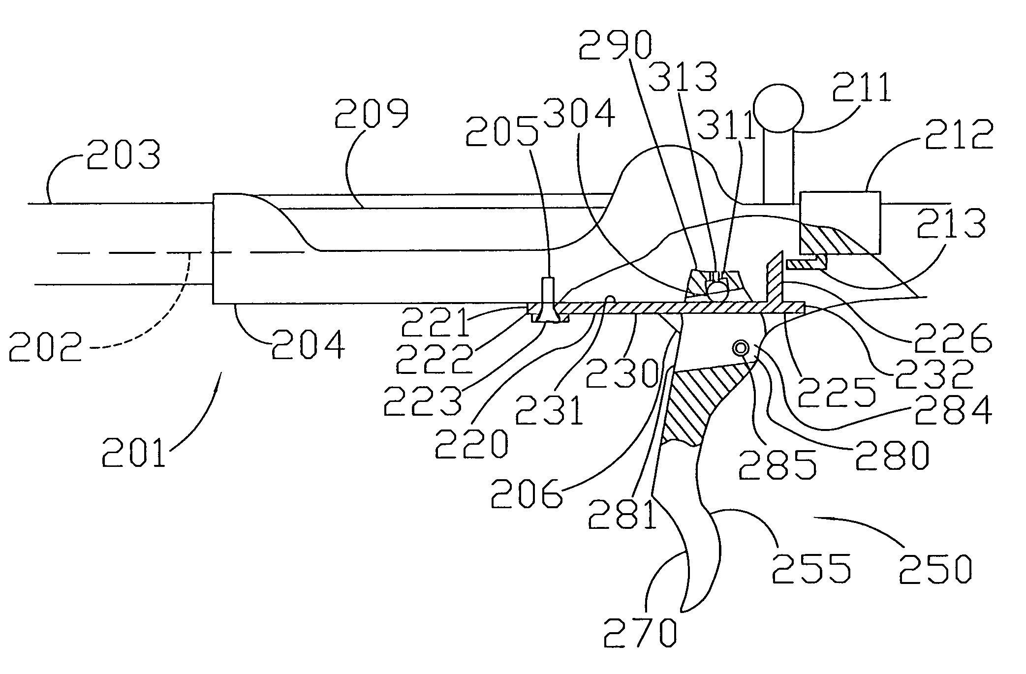
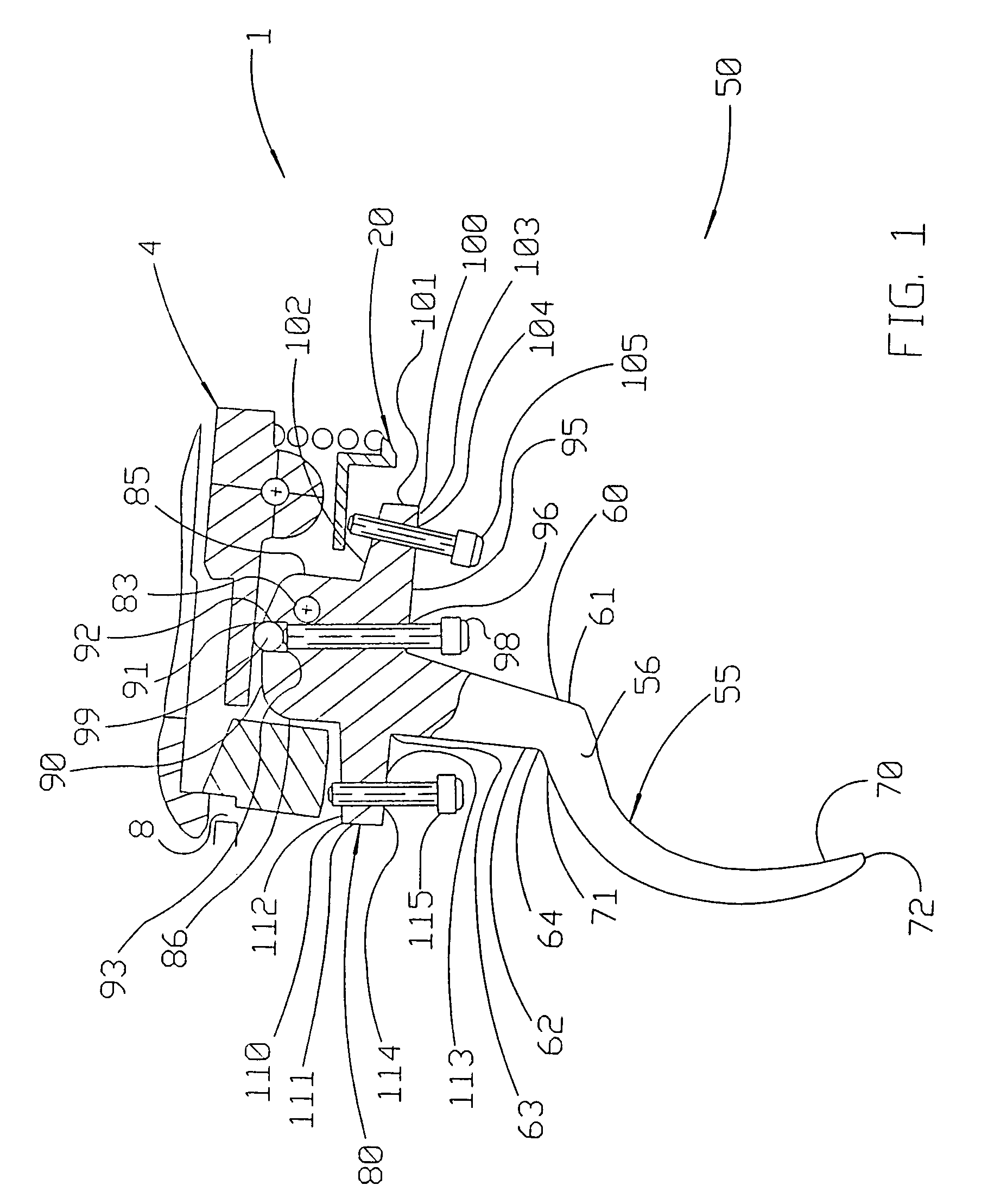
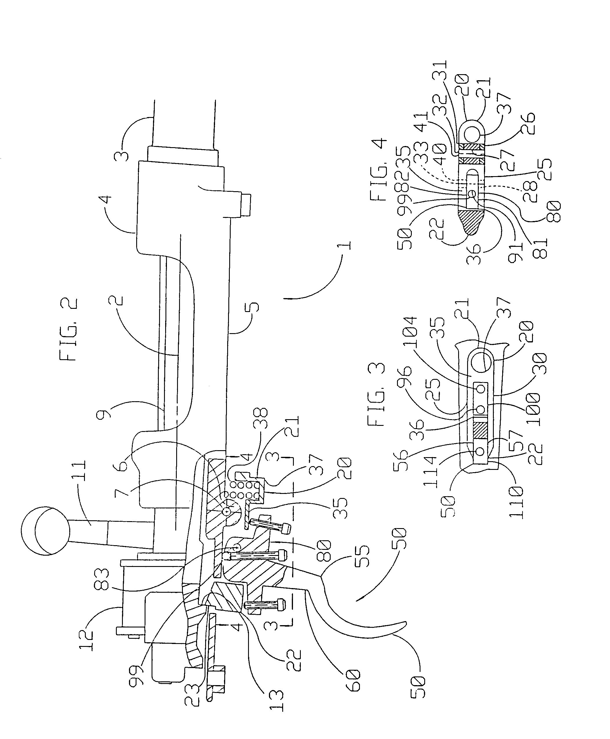
[0042]Referring first to FIGS. 1–4, reference numeral 50 indicates an embodiment of the anti-friction trigger of the present invention. The trigger 50 is shown and described in connection with a rifle 1. However, it is understood that the present invention can be used with other types of bolt-action guns without departing from the broad aspects of the invention. The rifle 1 has a longitudinal axis 2. Rifle 1 also has a barrel 3 with an inside diameter sufficient to accommodate a bullet. The barrel 3 has a free end from which a bullet projects and an opposite end. A receiver 4 is longitudinally aligned with the barrel ...


PUM


Abstract

The present invention relates to a gun trigger for use with a bolt-action gun. The trigger of the present invention has a finger element with an extension and a catch. The catch has a front strap and a rear strap. One or more openings are between the front and rear straps. One or more braces can be across the one or more openings. The trigger also has a head. A socket is formed in the top of the head, and a ball is received within the socket. The height of the ball relative the bottom of the socket can be adjusted. There is practically no friction between the trigger and a sear. The trigger of the present invention may be made by remanufacturing existing conventional triggers.

Description

[0001]This application is a Continuation-In-Part application of application having Ser. No. 10 / 199,425, filed Jul. 22, 2002 now U.S. Pat. No. 6,681,511.FIELD OF THE INVENTION[0002]The present invention relates to a gun trigger that reduces friction between the trigger and the sear or receiver of a gun. The trigger can have a front strap and a rear strap, and also is capable of setting trigger travel. The trigger can be a one-to-one replacement for a conventional trigger.BACKGROUND[0003]Military personnel and civilians alike desire accurate, yet simple and durable, firearms. One preferred type of firearm is a bolt-action rifle. Generally, a bolt-action rifle has a longitudinal axis. A barrel is in longitudinal alignment with a bolt. A cocking piece with a downwardly extending contact is at the rear end of the bolt. The bolt and cocking piece are within a receiver. The receiver has a bottom. One type of bolt-action rifle is a Mauser type rifle. In a Mauser or similar type rifle, the f...

Claims


Application Information

Patent Timeline
Patent Type & Authority Patents(United States)
IPC IPC(8): F41A19/00F41A19/16
CPCF41A19/16
Inventor HUBER, JOHN F.
Owner HUBER JOHN F
Why Eureka
Try Eureka