

Stranded wire twisting device of reinforcement binding machine
a technology of reinforcement binding machine and twisting device, which is applied in the direction of bundling machine details, wire tools, applications, etc., can solve the problems of solving problems, and achieve the effect of simplifying the construction of the twisting apparatus, reducing the number of parts thereof, and occupying spa
- Summary
- Abstract
- Description
- Claims
- Application Information
AI Technical Summary
Benefits of technology
Problems solved by technology
Method used
Image

Examples
Embodiment Construction
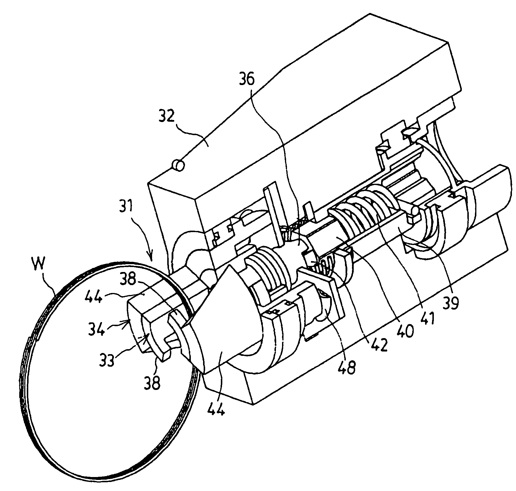
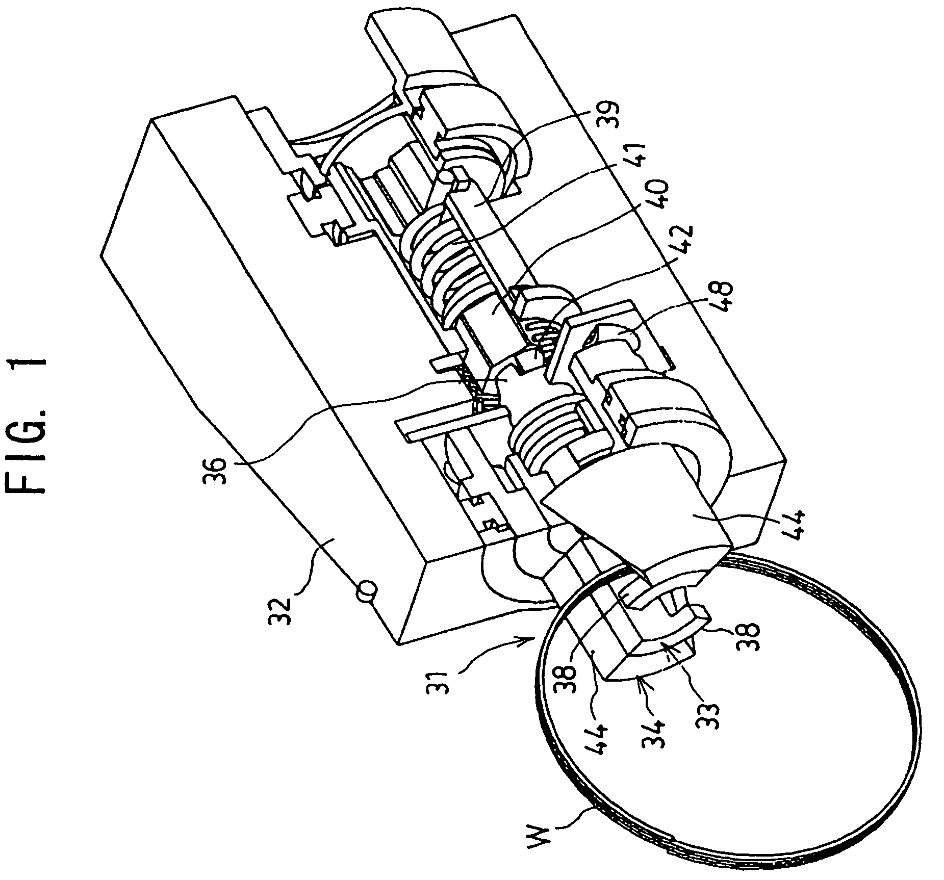
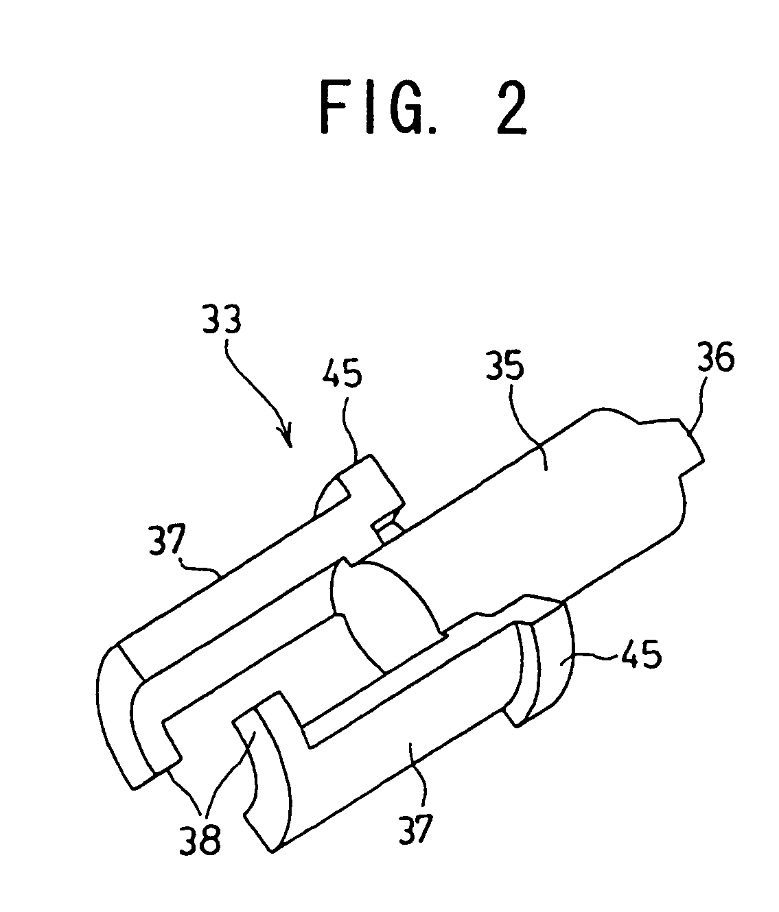
[0019]A mode of embodiment of this invention will now be described in detail with reference to the drawings. FIG. 1 shows a binding wire twisting apparatus 31 for reinforcing bar binding machines, and a reference numeral 32 denotes a bearing of a reinforcing bar binding machine, in which the bearing 32 of the binding wire twisting apparatus 31 is fitted. The binding wire twisting apparatus 31 is provided with a twisting shaft 33 connected to reduction gears of a twisting motor, and a sleeve (which will hereinafter be referred to as a remover 34) fitted around the twisting shaft 33. FIG. 2 shows a twisting shaft 33, and clutch claw 36 is formed at a rear end section of a shaft portion 35. A pair of forks 37 project forward from an outer circumferential surface of the shaft portion 35. Hooks 38 are provided to extend from front ends of the forks 37 and bent in the circumferential direction of the shaft, i.e., counter-clockwise in front view thereof. The outer surfaces of the forks 37 ...
PUM
| Property | Measurement | Unit |
|---|---|---|
| circumferential length | aaaaa | aaaaa |
| length | aaaaa | aaaaa |
| outer circumference | aaaaa | aaaaa |
Abstract
Description
Claims
Application Information