Fuel injection valve for internal combustion engines

a fuel injection valve and internal combustion engine technology, which is applied in the direction of fuel injection apparatus, spraying apparatus, feeding system, etc., can solve the problems of not being able to control the injection cross section of the known fuel injection valve, not being able to generate the closing force of the outer valve needle, and being relatively complicated and hence expensive to produce. , to achieve the effect of minimizing the leakage of fuel injection valves and high pressur

Inactive Publication Date: 2006-05-30
ROBERT BOSCH GMBH
View PDF14 Cites 19 Cited by
  • Summary
  • Abstract
  • Description
  • Claims
  • Application Information

AI Technical Summary

Benefits of technology

[0008]The fuel injection valve of the invention has the advantage over the prior art that both the inner and the outer valve needle can be triggered via only a single control valve. A control chamber is embodied in the housing and communicates with the high-pressure conduit and furthermore with a control pressure chamber. Through the pressure in the control chamber, a closing force is exerted at least indirectly on the outer valve needle. In the housing, there is a control valve by which the control chamber can be made to communicate with a leak fuel chamber, so that the pressure in the control chamber and, because of the communication with the control chamber, in the control pressure chamber as well can be lowered to markedly below the injection pressure via the control valve, so that the closing force on the inner and outer valve needle can be controlled. Via a suitable switching characteristic of the control valve and suitably dimensioned inlets and outlets from the control chamber and of its communication with the control pressure chamber, a separate triggering of the outer valve needle, or selectively of both valve needles, can be achieved.
[0009]In an advantageous feature of the subject of the invention, the control valve has a valve chamber, which communicates with the control chamber, and also has a valve member, which is controlled by an actuator. The actuator is advantageously embodied as an electric actuator and in particular as a piezoelectric actuator. As a result, the valve member can be controlled precisely, and the valve member can be moved directly to the desired position.
[0010]In a further advantageous feature, in a first switching position, the valve member cooperates with a first valve seat, and in a second switching position it cooperates with a second valve seat; in the first switching position, the valve chamber is sealed off from the leak fuel chamber, and in the second switching position it communicates with the leak fuel chamber. By means of this valve member, the pressure in the control chamber can be controlled precisely and without any significant time lag.
[0011]In a further advantageous feature, the valve chamber of the control valve can be made to communicate with the high-pressure conduit via a connecting conduit, and when the valve member is in contact with the second valve seat, it closes the connecting conduit. Upon relief of the control chamber, the connecting conduit thus becomes inoperative and does not impede the further function of the pressure regulation in the control chamber. Upon actuation of the control valve and upon motion of the valve member toward the first valve seat, the high-pressure conduit is uncovered, and fuel can flow at the injection pressure into the valve chamber and from there into the control chamber. As a result, after the end of the injection, a high pressure is built up very quickly in the control chamber, so that a strong closing force on the outer valve needle and thus also on the inner valve needle results.
[0012]In a further advantageous feature, an outer pressure piston is disposed in a housing; it communicates with the outer valve needle, and its end face defines the control chamber. In this way, as a result of the pressure in the control chamber, a hydraulic force on the end face of the outer pressure piston is produced, so that a closing force is exerted on the outer valve needle. Because of the separation of the function of the pressure face subjected to pressure and of the valve needle, the two parts can be optimized separately from one another.
[0013]In still another advantageous feature, the outer pressure piston, in the opening stroke motion of the outer valve needle, comes to rest on a wall of the control chamber, interrupting the communication of the control chamber with the high-pressure conduit. As a result, when the fuel injection valve is open, fuel no longer flows into the control chamber, and thus the leak fuel losses of the fuel injection valve are minimized.
[0014]In another advantageous feature, the control pressure chamber is embodied in the outer pressure piston and communicates with the control chamber through a bore in the outer pressure piston. This construction allows direct triggering of the inner valve needle, which is located inside the outer valve needle, and furthermore results in a very space-saving construction.
[0015]In an advantageous feature, a pressure markedly lower than the injection pressure, this lower pressure preferably being atmospheric pressure, prevails in the leak fuel chamber. The lower the pressure in the leak fuel chamber, the greater are the pressure differences from the injection pressure, so that correspondingly greater forces on the inner and outer valve needle can also be achieved, and hence shorter switching times.

Problems solved by technology

The known fuel injection valve has the disadvantage, however, that the closing force on the outer valve needle is not generated hydraulically but rather via a fixedly prestressed closing spring.
Moreover, the prior art has the disadvantage that the control valve that regulates the pressure in the control chamber is embodied as a 3 / 2-way valve with a slide seat, so that it is relatively complicated and hence expensive to produce.
It is thus not possible in the known fuel injection valve to control the injection cross section arbitrarily.

Method used


Image

  • Fuel injection valve for internal combustion engines
  • Fuel injection valve for internal combustion engines
  • Fuel injection valve for internal combustion engines

Examples


Embodiment Construction

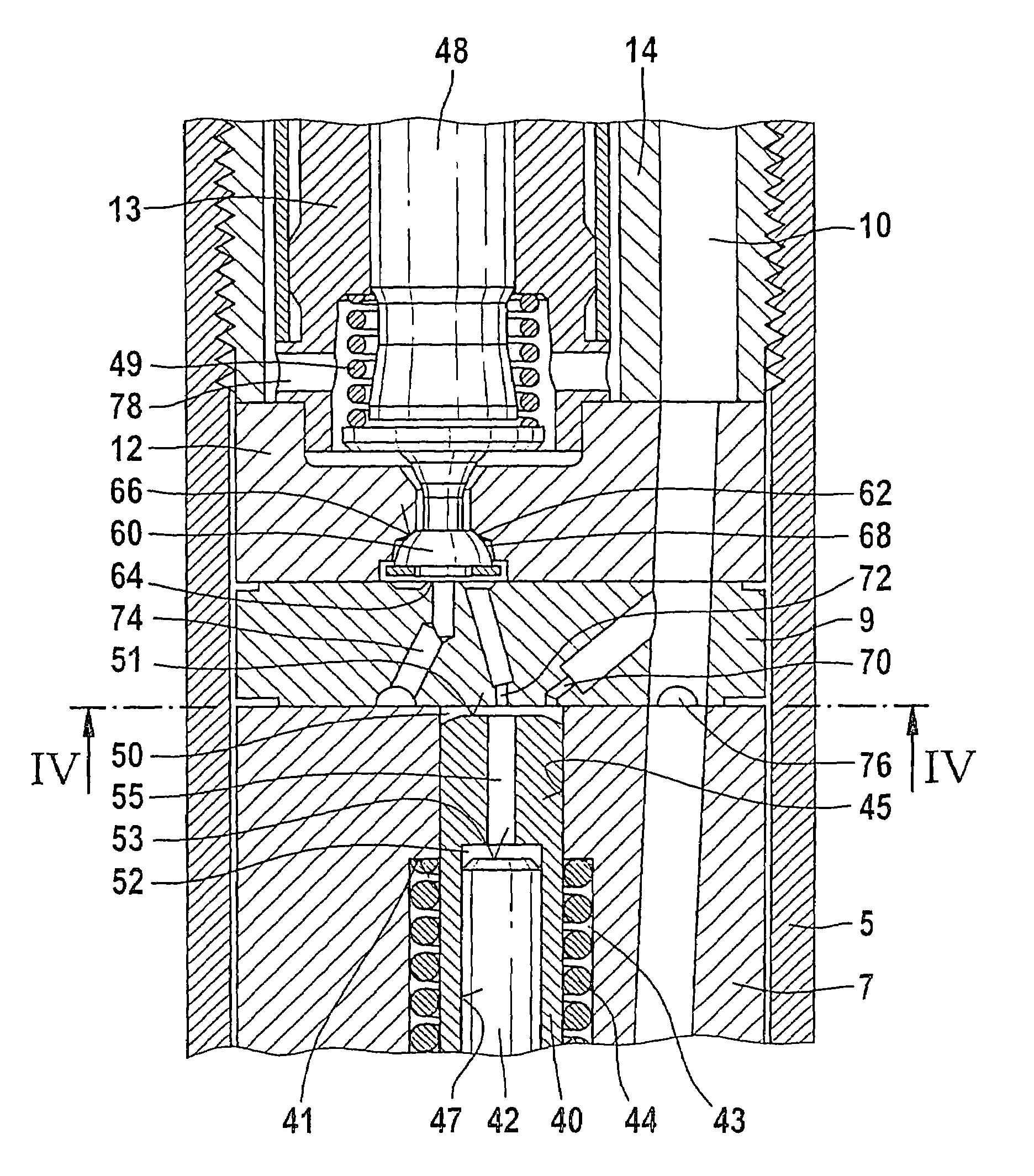
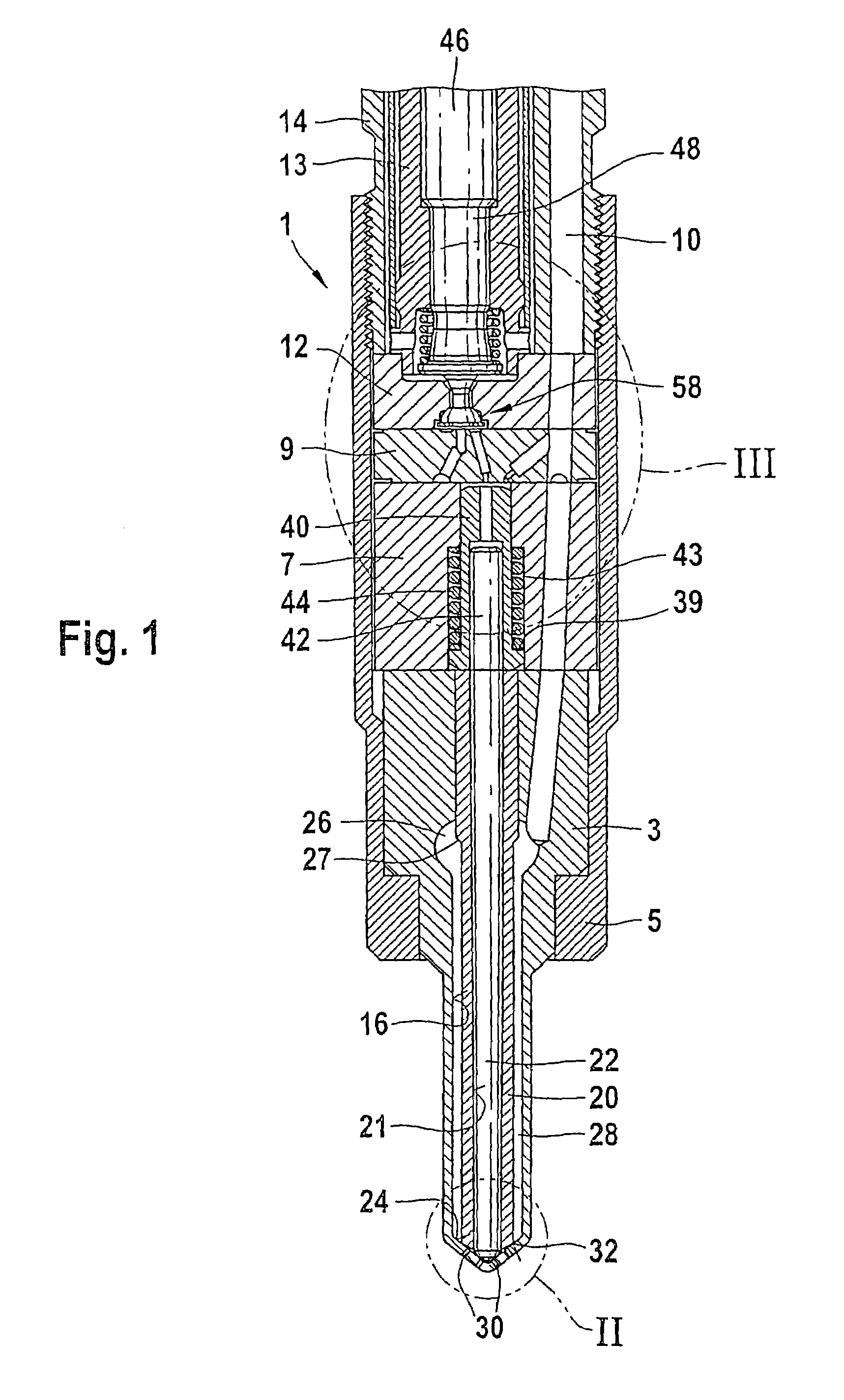
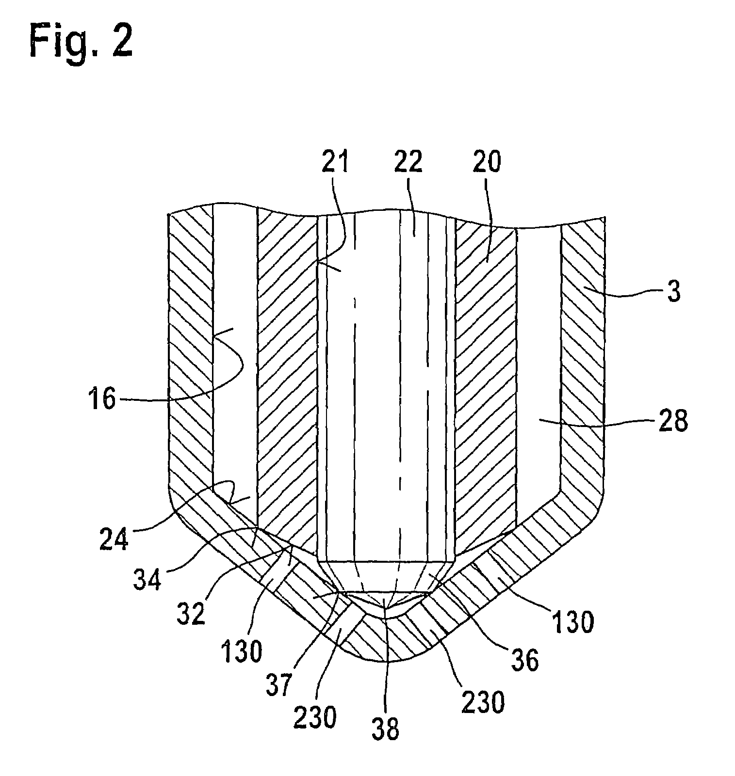
[0021]In FIG. 1, a longitudinal section is shown through a fuel injection valve of the invention, the fuel injection valve having a housing 1, which has a valve body 3, an intermediate body 7, an intermediate disk 9, a control body 12, and a retaining body 14, with these components each resting on one another in the order recited. All these parts of the housing 1 are pressed against one another by their contact faces by means of a lock nut 5. A high-pressure conduit 10 embodied in the housing 1 communicates with a high-pressure fuel source, not shown in the drawing, and extends as far as the inside of the valve body 3 through the retaining body 14, the control body 12, the intermediate disk 9, and the intermediate body 7. In the valve body 3, the high-pressure conduit 10 discharges into a pressure chamber 26, which is embodied as a radial enlargement of a bore 16 embodied in the valve body 3. The bore 16, on its end toward the combustion chamber, is closed off by a seat face 24, and...


PUM


Abstract

A fuel injection valve for internal combustion engines, having a housing in which an outer valve needle and an inner valve needle guided in it are disposed in a bore. The outer valve needle controls an outer row of injection openings, and the inner valve needle controls an inner row of injection openings, to which rows of injection openings fuel is delivered at an injection pressure through a high-pressure conduit embodied in the housing. A control pressure chamber in the housing can be made to communicate with the high-pressure conduit, and by means of its pressure, a closing force is exerted at least indirectly on the inner valve needle. The high-pressure conduit communicates with a control chamber, by whose pressure a closing force is exerted at least indirectly on the outer valve needle, and the control chamber communicates with the control pressure chamber. A control valve is disposed in a housing, and by means of the control valve, the control chamber can be made to communicate with a leak fuel chamber.

Description

CROSS-REFERENCE TO RELATED APPLICATIONS[0001]This application is a 35 USC 371 application of PCT / DE 03 / 00210 filed on Jan. 27, 2003.BACKGROUND OF THE INVENTION[0002]1. Field of the Invention[0003]The invention is directed to an improved fuel injection valve for internal combustion engines.[0004]2. Description of the Prior Art[0005]One fuel injection valve known for instance from published, nonexamined German patent application DE 41 15 477 A1 includes an outer valve needle and an inner valve needle guided in it are located in a housing. Both valve needles cooperate, by their end toward the combustion chamber, with a valve seat face in which there are two rows of injection openings. The outer row of injection openings is controlled by the outer valve needle, and the inner row of injection openings is correspondingly controlled by the inner valve needle. Through a high-pressure conduit embodied in the housing, the injection openings are supplied with fuel at high pressure, which emerg...

Claims


Application Information

Patent Timeline
Patent Type & Authority Patents(United States)
IPC IPC(8): F02M63/00F02M61/00F02M61/10F02M45/08F02M47/00F02M47/02F02M51/00F02M51/06F02M61/18
CPCF02M45/086F02M47/027F02M2200/46F02M2200/21F02M61/18F02M45/08F02M47/02
Inventor SANDER-POTZ, LEGAL REPRESENTATIVE, MAIKEPOTZ, LEGAL REPRESENTATIVE, WENDELINBOEHLAND, PETERKUEGLER, THOMASKOENINGER, ANDREASNUNIC, PREDRAGPOTZ, DECEASED, DETLEV
Owner ROBERT BOSCH GMBH
Why Eureka
Try Eureka