Component mounting assembly

a technology of mounting assembly and component, which is applied in the directions of transportation and packaging, load securing, transportation items, etc., can solve the problems of disadvantageous cost, labor intensive, and inconvenient installation, service or repair, and achieve the effect of reducing mass, cost and labor efficiency, and reducing cycle time and piece cos

Inactive Publication Date: 2006-05-30
GM GLOBAL TECH OPERATIONS LLC
View PDF4 Cites 3 Cited by
  • Summary
  • Abstract
  • Description
  • Claims
  • Application Information

AI Technical Summary

Benefits of technology

[0005]The assembly in accordance with the present invention preferably attaches to the body panel by utilizing existing indentation or slots formed in the body panel. The rail member preferably attaches at three places along the entire length of the rail. The fastening member eliminates any need to have any backing plates or welded on plates / nuts for installation. The assembly also allows the customer to add this entire feature even if the original product was not ordered with it. The backing plate of the fastening member becomes a solid pillar when engaged with the rail to form a solid joint. The rail member utilizes a dual track system that allows a plurality of attachments to bypass each other while in use.
[0006]The present invention provides an assembly that eliminates mass, cycle time, and piece cost. The fastening member both attaches the rail, and takes the place of traditional weld-on backing plates. The rail member is utilized as a structural member as well to distribute loading across all three attachment points.
[0007]The assembly in accordance with the present invention advantageously provides an assembly that can be releasably attached to the mounting surface of the vehicle body panel without requiring any further structural upgrade to the mounting surface. The assembly for mounting at least one component is cost and labor effective and user friendly for installation, service or repair.

Problems solved by technology

Welding the backing plate to the body panel, however, is disadvantageously costly, labor intensive and is not user friendly for installation, service, or repair.

Method used


Image

  • Component mounting assembly
  • Component mounting assembly
  • Component mounting assembly

Examples


Embodiment Construction

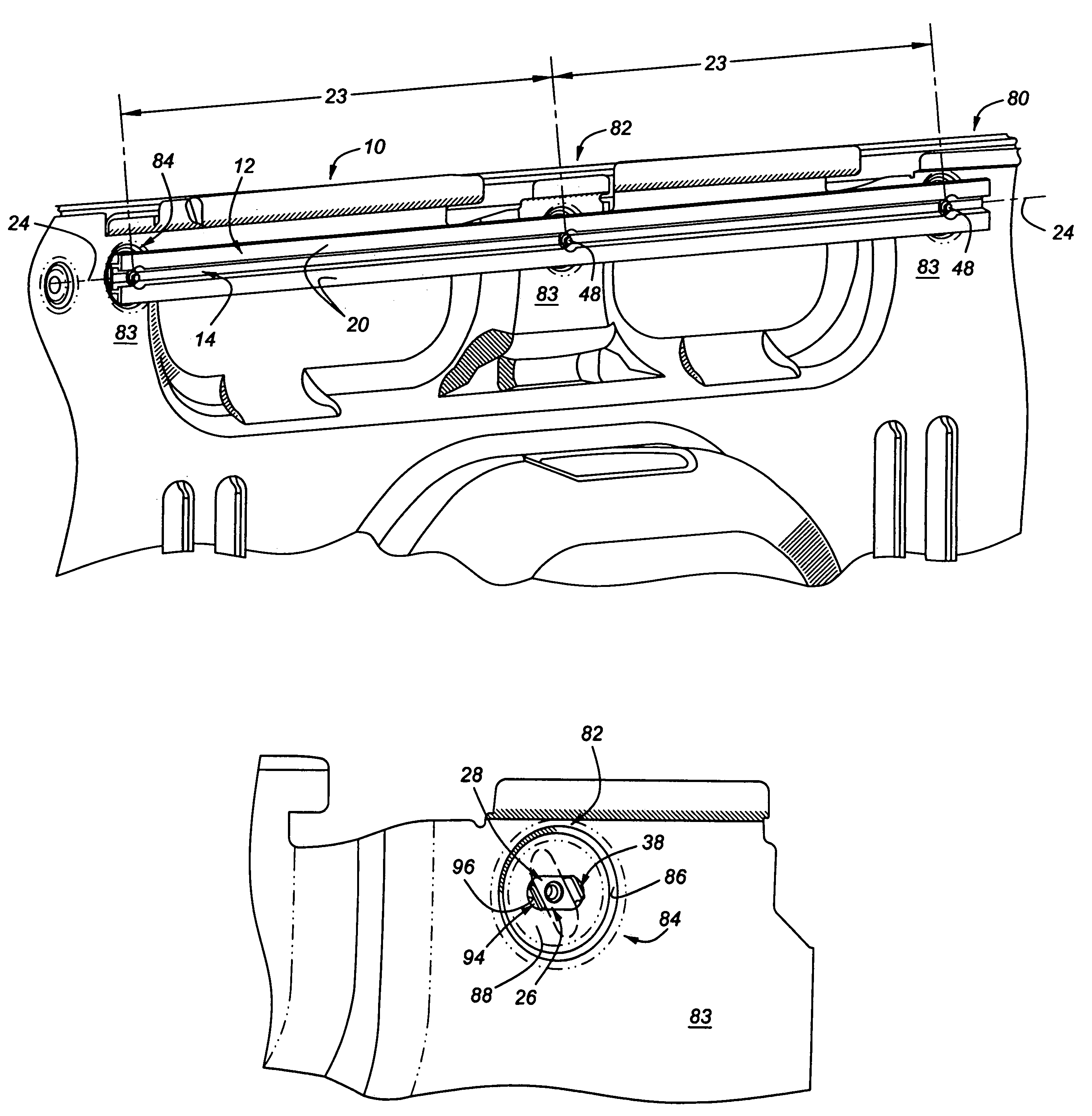
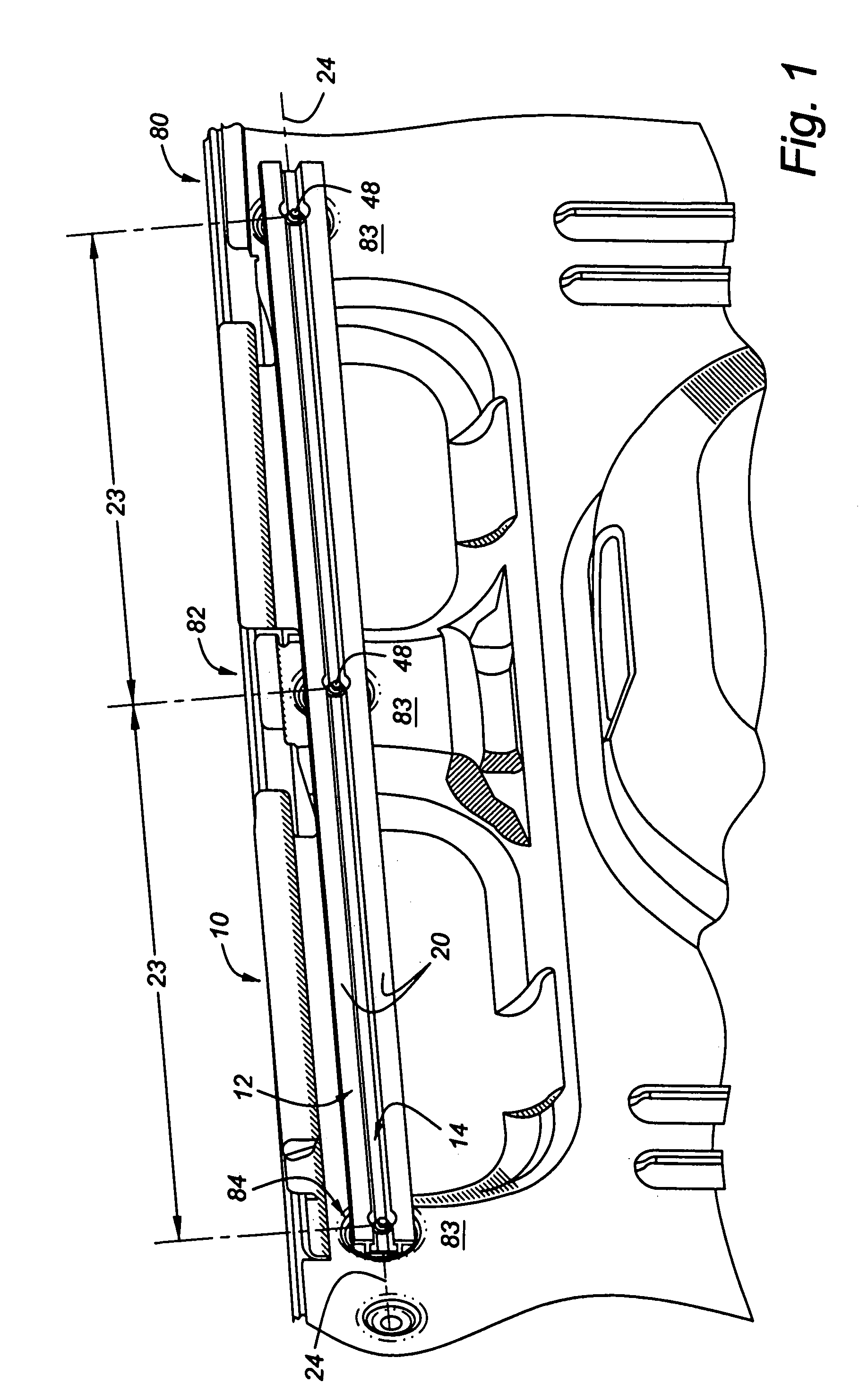
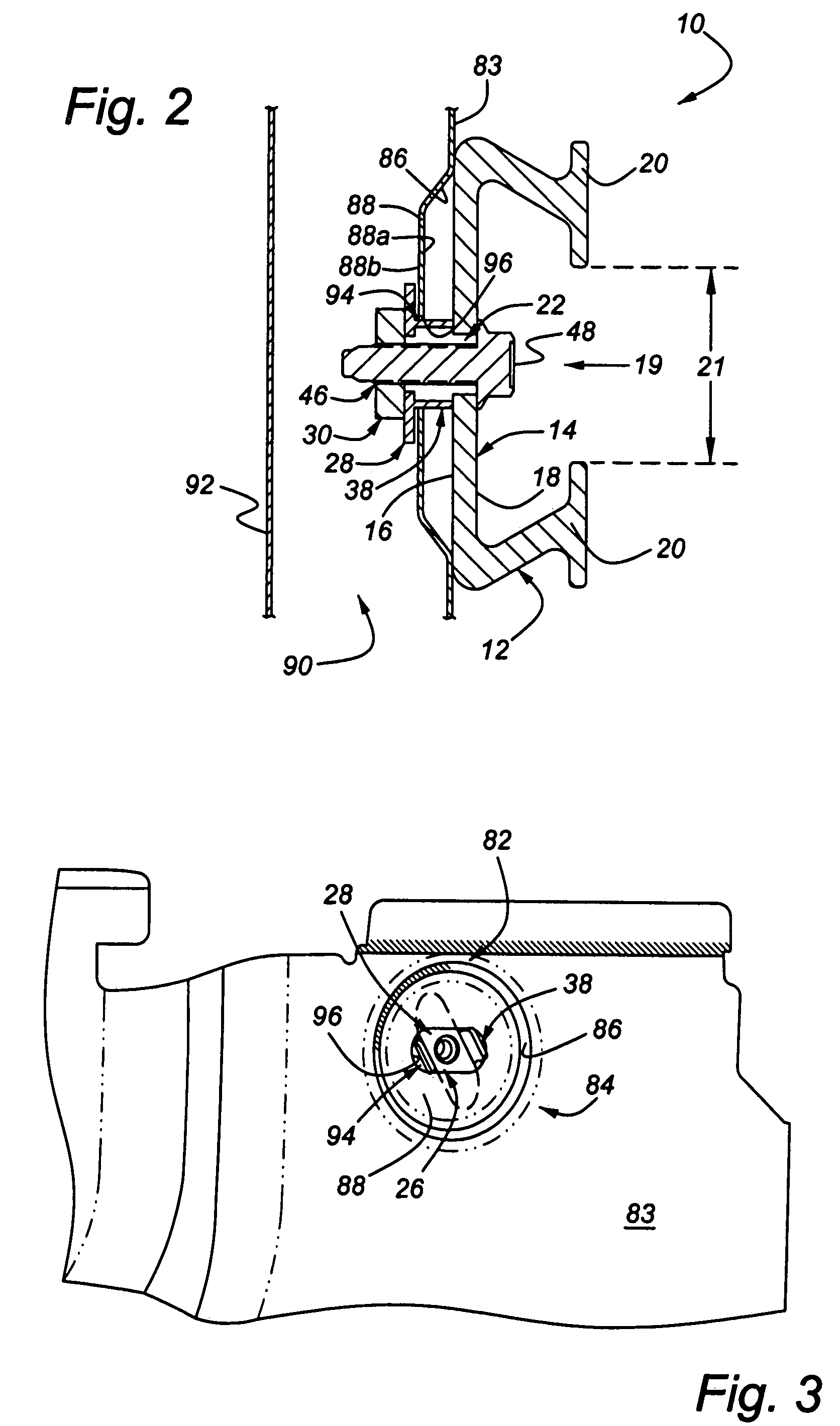
[0013]Referring now to FIGS. 1 and 2, an assembly for mounting at least one component thereto in accordance with the present invention is indicated generally at 10. The assembly 10 includes a rail member 12 having a base portion 14 that includes a first side 16 and a second side 18. A pair of flanges 20 extends outwardly from the second side 18 of the base portion 14. The flanges 20 are preferably T-shaped in cross-section. A plurality of apertures 22 extend through the first side 16 and second side 18 of the base member 14. Each of the apertures 22 are preferably evenly spaced apart along the rail member 12 by a predetermined distance 23. Alternatively, the distances 23 may be chosen or varied according to the specific requirements for the assembly 10. Preferably, the rail member 12 is an elongated member along a longitudinal axis 24 thereof. Alternatively, the rail member 12 is formed of any length suitable for attaching components thereto, discussed in more detail below. The flan...


PUM


Abstract

An assembly adapted to be releasably attached to a mounting surface on a body panel of an automotive vehicle for mounting at least one component thereto includes at least one elongated rail member having a base portion that includes a first side adapted to be located adjacent to the mounting surface and an opposed second side. The rail member includes a pair of spaced apart flanges extending outwardly from the second side of the base portion. The base portion includes at least one aperture extending therethrough. The assembly also includes at least one fastening member that is adapted to be retained in the body panel by a retaining feature. The fastening member includes a backing plate portion having at least one flange extending therefrom and an aperture extending therethrough for receiving a fastener for releasably attaching the assembly to the mounting surface.

Description

BACKGROUND OF THE INVENTION[0001]The present invention relates generally to mounting assemblies and, in particular, to an assembly adapted to be releasably attached to a mounting surface on a body panel of an automotive vehicle for mounting at least one component thereto.[0002]It is common in vehicles to provide a location to stow cargo and / or mount attachments thereto. Cargo hooks, cargo clips, bag hooks are all well known for storage locations. Occasionally, a more robust connection is desired. Such a connection can include a rail member attached to a body panel of the vehicle by a plurality of bolts or screws. Prior art rails, however have been attached to the body panel by welding a backing plate on to the body panel to eliminate any possibility of turning while the bolt or screw is being tightened. Welding the backing plate to the body panel, however, is disadvantageously costly, labor intensive and is not user friendly for installation, service, or repair.[0003]It is desirable...

Claims


Application Information

Patent Timeline
Patent Type & Authority Patents(United States)
IPC IPC(8): B60P7/08
CPCB60R11/00B60P7/0815
Inventor JUTILA, BRIAN J.VAN BUREN, BRIAN D.SIENKIEWICZ, DENNIS
Owner GM GLOBAL TECH OPERATIONS LLC
Why Eureka
Try Eureka