
Turbine blade and turbine

a turbine blade and blade technology, applied in the field of moving blades, can solve the problems of friction loss, flow separation, and difficulty in strictly classifying actual turbine stages in such a manner, and achieve the effects of increasing secondary flow loss, increasing the curvature of the blade suction side, and increasing the thickness of the boundary layer

Inactive Publication Date: 2006-05-30
MITSUBISHI HITACHIPOWER SYST LTD
View PDF7 Cites 12 Cited by
  • Summary
  • Abstract
  • Description
  • Claims
  • Application Information

AI Technical Summary

Benefits of technology

The present invention provides a turbine moving blade that can reduce aerodynamic losses, such as blade profile loss and secondary flow loss. The blade profile is designed to have a pressure distribution that drops in two stages in the area from the leading edge to the minimum pressure point. This design helps to minimize the growth of the boundary layer and suppress the secondary flow loss, resulting in lower blade profile and secondary flow losses.

Problems solved by technology

However, it is difficult to strictly classify actual turbine stages in such a manner.
Further, in the blade profile in which a maximum blade loading location is located on the leading edge side (FORE-LOADED), a decelerated flow (adverse pressure gradient) area extending from the blade suction side maximum velocity point (minimum pressure point) of the velocity distribution toward the trailing edge becomes relatively long, which makes the boundary layer grow, increasing the thickness of the boundary layer at the end of the trailing edge, thus causing a friction loss.
If such a cascade is specifically applied to an impulse stage or a low-reaction stage of a moving blade, a flow cannot catch up with the large curvature of the blade suction side, which may result in the flow being separated and causing an excessive loss.
Furthermore, since a secondary flow results from a pressure difference between the blade suction side and the blade pressure side, the further out on the leading edge side a maximum blade loading position is, the earlier a secondary flow vortex starts to grow, which tends to increase the secondary flow loss.

Method used


Image

  • Turbine blade and turbine
  • Turbine blade and turbine
  • Turbine blade and turbine

Examples


Embodiment Construction

[0027]A turbine moving blade which is an embodiment of the present invention will be described below with reference to the accompanying drawings. A turbine moving blade according to the present invention is applicable to a steam turbine, gas turbine or the like. In the following description, a turbine moving blade for use in a steam turbine will be used as an example.

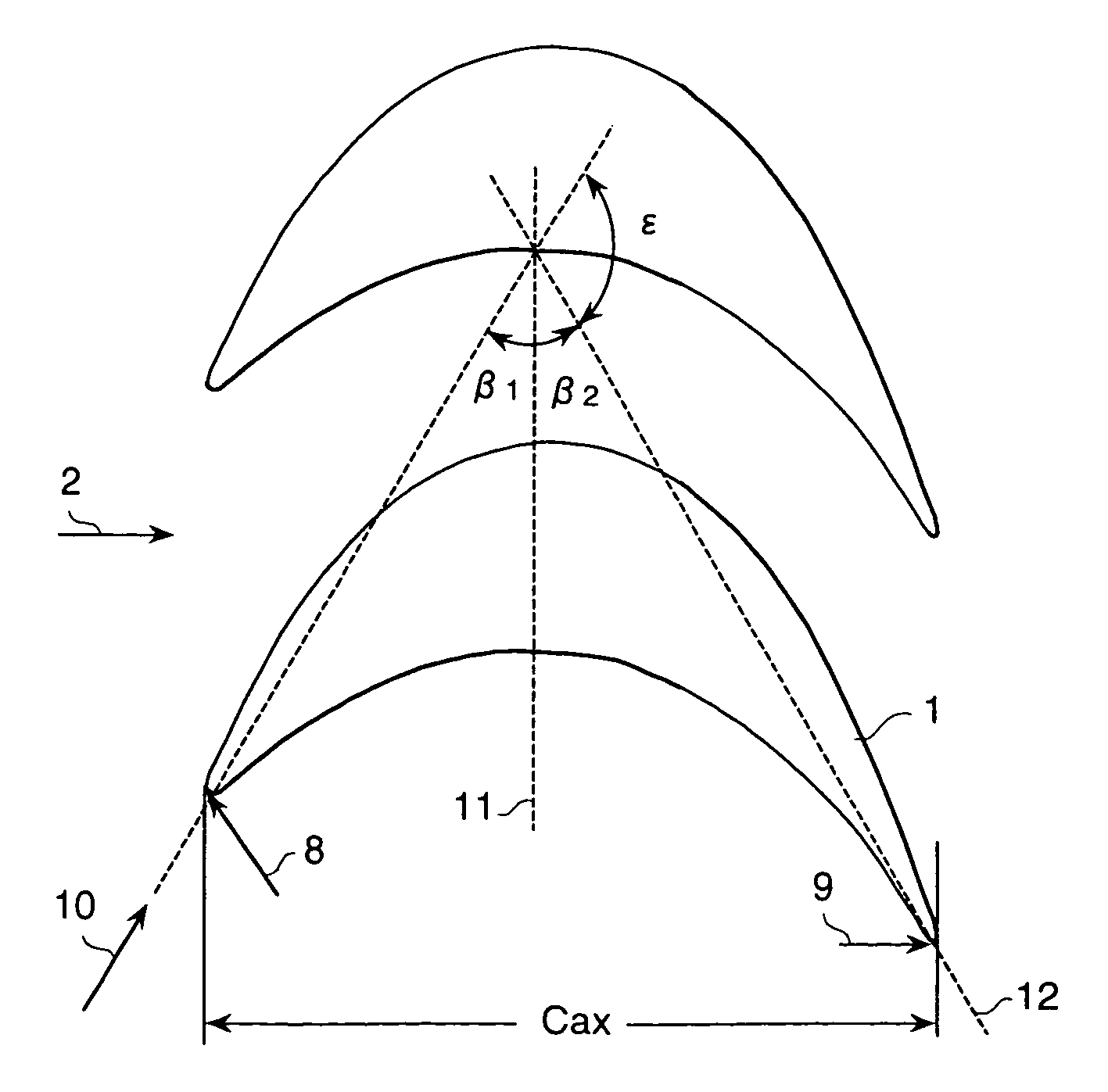
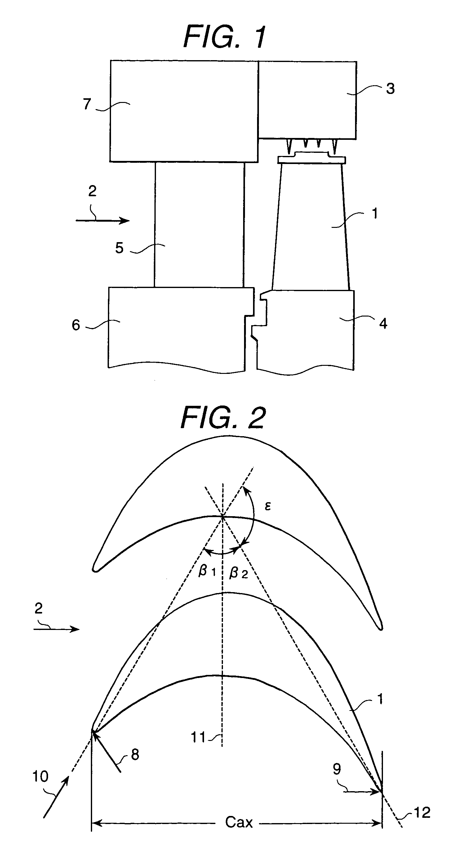
[0028]FIG. 1 is a transverse cross-sectional view of a turbine moving blade in this embodiment. In the drawing, there are shown a moving blade 1, steam 2, a fixing part 3 which supports the sealing structure of a moving blade tip portion, a disk 4 which fixes the moving blade 1 to a rotor, a stationary blade (nozzle) 5 which induces the steam 2 to the moving blade 1, an annular inner ring 6 which cramps an inside edge portion of the stationary blade 5, and an annular outer ring 7 which fixes an outside edge portion of the stationary blade 5 to a casing. A plurality of moving blades 1 are disposed with respect to the cir...


PUM


Abstract

The pressure distribution curve of the blade suction-side surface excluding the leading edge portion and the trailing edge portion drops in two stages in the area from the leading edge to the minimum pressure point.

Description

[0001]This is a continuation application of U.S. Ser. No. 10 / 079,862, filed Feb. 22, 2002 now U.S. Pat. No. 6,776,582.BACKGROUND OF THE INVENTION[0002]1. Field of the Invention[0003]The present invention relates to a moving blade for use in a steam turbine, gas turbine or the like.[0004]2. Description of Prior Arts[0005]It is possible to save energy resources and reduce emission of carbon dioxide and so forth by suppressing a blade profile loss and a secondary flow loss generated in a turbine blade thereby increasing the internal efficiency in a turbine stage.[0006]The well-known prior art to reduce such a turbine moving blade loss has been disclosed, for example, in JP A No. 61-232302, JP A No. 05-187202 and JP A No. 2000-345801.[0007]The above-mentioned JP A No. 61-232302 discloses a blade profile related to a turbine cascade for use in a jet engine or a gas turbine engine and having so-called “FORE-LOADED” type velocity distribution (pressure distribution) wherein the blade profi...

Claims


Application Information

Patent Timeline
Patent Type & Authority Patents(United States)
IPC IPC(8): F04D29/54F01D5/14
CPCF01D5/141F01D5/142Y10S416/02F05D2240/301Y02T50/673Y02T50/60
Inventor SEGAWA, KIYOSHISHIKANO, YOSHIOYAMAZAKI, YOSHIAKISENOO, SHIGEKINAKAYAMA, YOSHIHARU
Owner MITSUBISHI HITACHIPOWER SYST LTD
Learn More