Multi-fan assembly comprising a servomotor driven vertical oscillation means for each fan

a technology of vertical oscillation and multi-fans, which is applied in the direction of piston pumps, rotors, vessel construction, etc., can solve the problems of laborious and time-consuming, limited cooling effect of multi-fan assemblies of this kind, and achieve the effect of strong current and fast rotation

Inactive Publication Date: 2006-05-30
CHEN CHIA TEH
View PDF8 Cites 10 Cited by
  • Summary
  • Abstract
  • Description
  • Claims
  • Application Information

AI Technical Summary

Benefits of technology

[0016]3. On a rotary assembly of the multi-fan assembly of the present invention is provided with a speed control unit, which including: a motor, a gear cluster and a current control unit. The current control unit controls the current so as to control the rotating speed of the motor, through the differential motion of the gear cluster, the rotary assembly is driven to revolve. The stronger the current is, the faster the revolution will be. By this way, the revolution speed of the multi-fan assembly can be adjusted and controlled and it can be controlled by method of remote control or by wire control.
[0017]4. In a like manner as 2, the revolution of the multi-fan assembly of the present invention can be stopped by cutting off the current, such that horizontal revolution can be instantly stopped and fixed at any position according to user's needs.

Problems solved by technology

First, due to the pitching angle of the member fans 91 is fixed and unchangeable during the revolution of the rotary assembly 92, the cooling effect of the multi-fan assembly of this kind is limited.
Second, since the pitching angle of the member fans 91 only can be adjusted by manual way, it is very laborsome and time-consuming.
Third, the revolution speed is unadjustable. If the revolution speed is fixed, the users sitting around a bigger table will enjoy less cooling airflow provided by the member fans 91 than the users who sit around a smaller table. That is to say, the revolution speed should be adjusted at a direct proportion to the working radius of the member fans 91, so as to provide enough airflow for the respective users. The revolution of the conventional multi-fan assembly is driven by the rotation of the member fans, it is found in practices that the bigger the working radius of the member fans is, the slower the revolution speed will be, and vice versa. However, this characteristic of the conventional multi-fan assembly just runs counter to the user's needs. In order to maintain a constant cooling frequency, the bigger table with larger working radius need to revolve at a faster speed, so that the sitting persons around the bigger table will enjoy the same frequency of cooling effect.

Method used


Image

  • Multi-fan assembly comprising a servomotor driven vertical oscillation means for each fan
  • Multi-fan assembly comprising a servomotor driven vertical oscillation means for each fan
  • Multi-fan assembly comprising a servomotor driven vertical oscillation means for each fan

Examples


Embodiment Construction

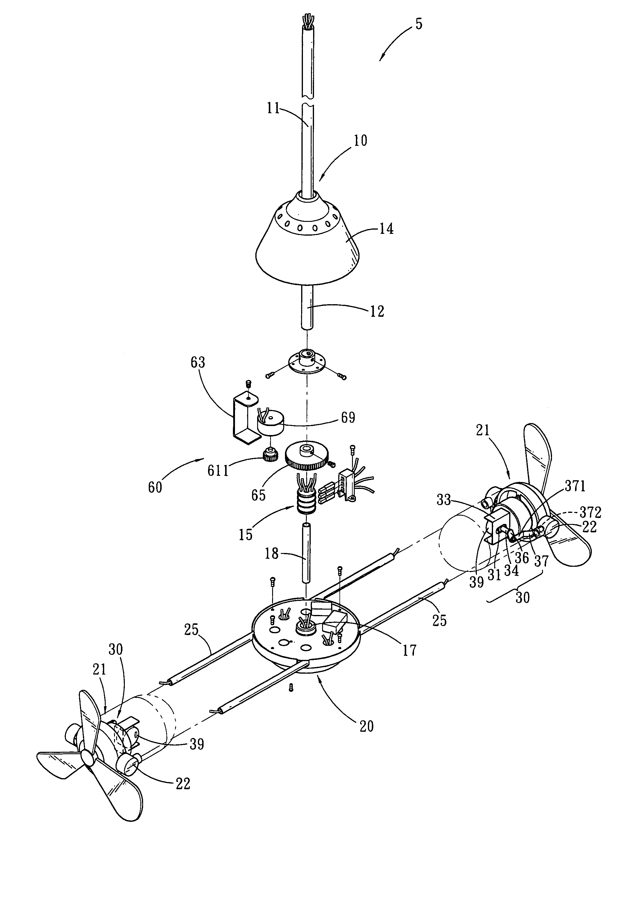
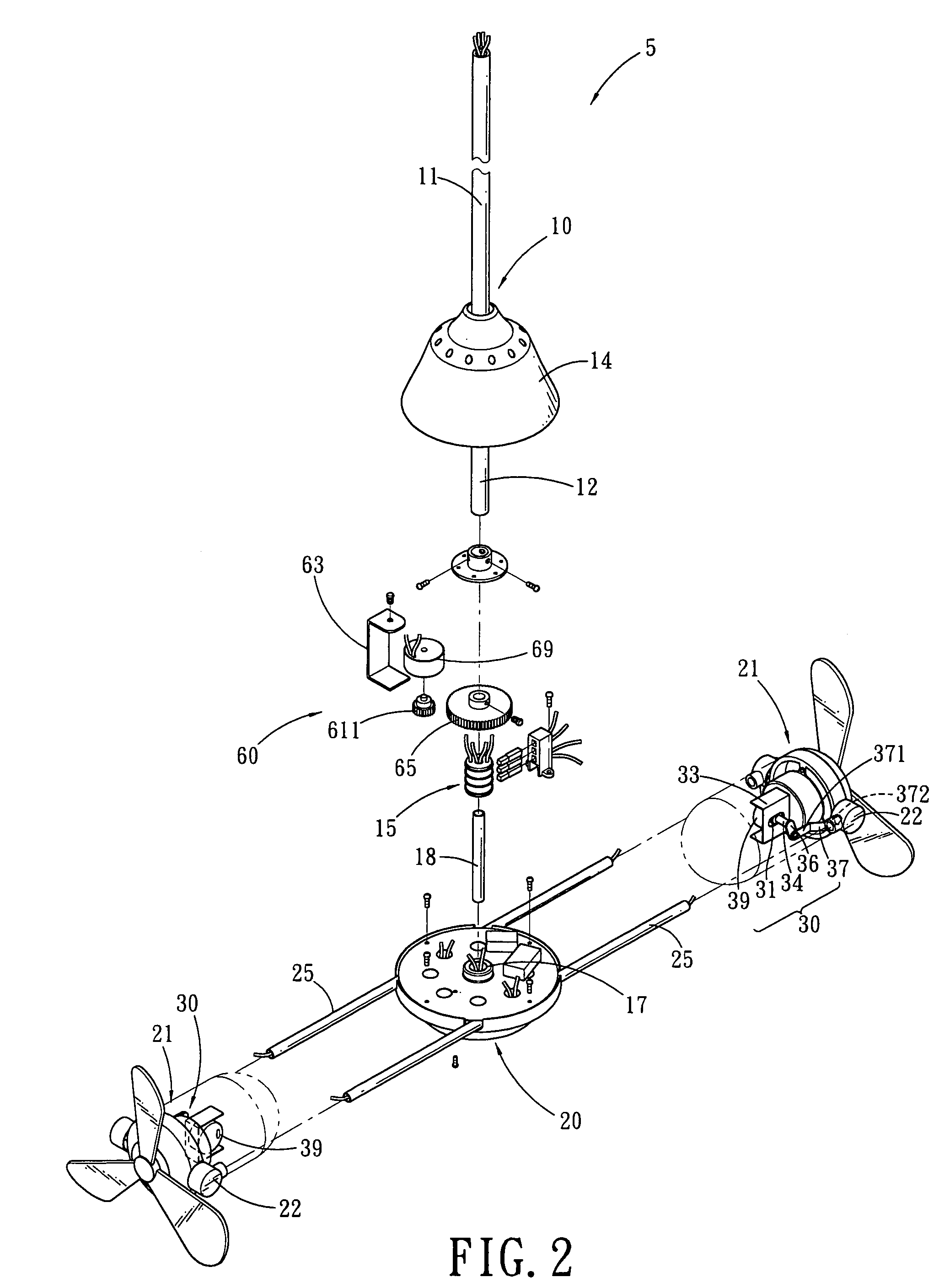
[0024]Referring to FIGS. 2–5, wherein a multi-fan assembly 5 in accordance with a first embodiment of the present invention is shown and generally comprising: a down rod assembly 10, a rotary assembly 20, a pair of vertical oscillating means 30 and a speed control device 60.

[0025]The down rod assembly 10 includes a down rod 11 and a shaft 12. The down rod 11 has a first end for fixing to ceiling wall and has a second end provided with a canopy 14. Inside of the canopy 14 thereof a transmission unit 15 is disposed. The shaft 12 is connected to the second end of the down rod 11 and covered by the canopy 14.

[0026]The rotary assembly 20, via a shaft bearing 17, is fixed to the lower end of the shaft 12 of the down rod assembly 10 and the canopy 14 of the down rod assembly 10 covers the top end of the rotary assembly 20. At both sides of the rotary assembly 20 fixed arms 25 are disposed respectively, on each fixed arm 25 is provided with a member fan 21, which is fixed thereon by virtue ...


PUM


Abstract

A multi-fan assembly includes: a down rod assembly having a first end for fixing to a ceiling wall and having a second end provided with a canopy, a rotary assembly being fixed to a lower end of the down rod assembly and covered by the canopy. At both sides of the rotary assembly is provided with a fixed arm for connecting with a member fan respectively, a pair of vertical oscillating means are disposed between the fixed arm and the member fan, and a speed control device is mounted on the rotary assembly and then covered by the canopy of the down rod assembly.

Description

BACKGROUND OF THE INVENTION[0001]1. Field of the Invention[0002]The present invention relates to a multi-fan assembly, and more particularly to a multi-fan assembly wherein the member fans of which can vertically oscillate while revolving about the common shaft of the multi-fan assembly, both of the pitching angle and the revolution of the member fans can be adjusted and fixed instantly by method of remote control or wire control.[0003]2. Description of the Prior Arts[0004]To avoid confusion during the course of this presentation, here are definitions for some words used in following descriptions as below:[0005]Rotation: the spinning of fan blades of the member fan rounds its own axis or the circular movement of a rotatable member moving round a central shaft.[0006]Revolution: the circular movement of two or more member fans rotating about a common central main shaft.[0007]Cooling frequency: the member fan to finish a whole circle revolution.[0008]Conventional multi-fan assembly is ...

Claims


Application Information

Patent Timeline
Patent Type & Authority Patents(United States)
IPC IPC(8): B64C11/16F04D25/08F04D25/10F04D25/16
CPCF04D25/088F04D25/166F04D25/105
Inventor CHEN, CHIA-TEH
Owner CHEN CHIA TEH
Why Eureka
Try Eureka