Distributed, load sharing power supply system for IC tester

a technology of power supply system and integrated circuit, which is applied in the direction of electronic circuit testing, measurement devices, instruments, etc., can solve the problems of inability to provide adequate voltage regulation, difficulty in regulating voltage of power supply, and inability to meet the requirements of voltage regulation

Inactive Publication Date: 2006-05-30
CREDENCE SYSTEMS
View PDF5 Cites 31 Cited by
  • Summary
  • Abstract
  • Description
  • Claims
  • Application Information

AI Technical Summary

Problems solved by technology

The highly cyclic nature of a CMOS IC's current demand makes it difficult for a power supply to regulate the voltage at the IC's power input terminal, particularly for a high current IC where modest impedances between the power supply and the IC's power input terminal can produce a large periodic variation in supply voltage at the power input terminal.
Such voltage variation can be reduced to acceptable limits by connecting a large regulating capacitor to the IC's power input terminal, but as IC current demand continues to increase, the amount of capacitance needed to provide adequate voltage regulation becomes impractically large.

Method used


Image

  • Distributed, load sharing power supply system for IC tester
  • Distributed, load sharing power supply system for IC tester
  • Distributed, load sharing power supply system for IC tester

Examples


Embodiment Construction

[0020]The invention relates to a power supply system for an integrated circuit (IC) tester. While the specification describes at least one exemplary embodiment of the invention considered to be a best mode of practicing the invention, the invention is not limited to the exemplary embodiment(s) described below or to the manner in which the exemplary embodiments operate.

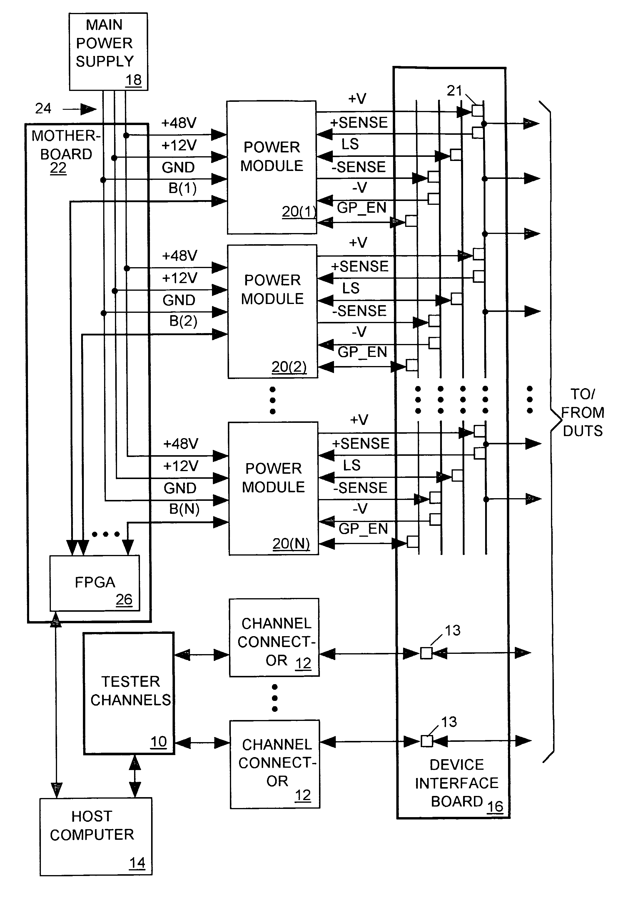
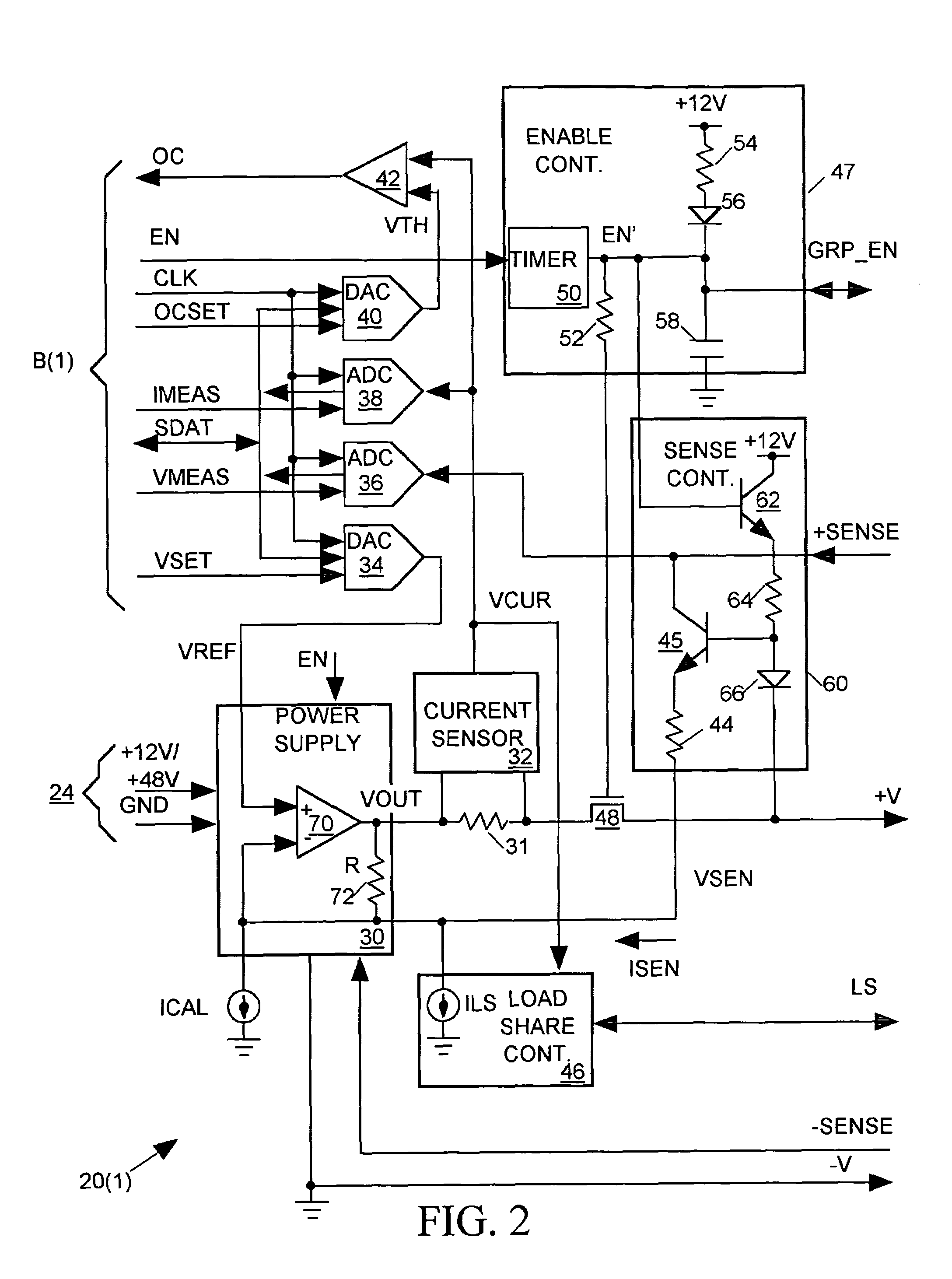
[0021]An IC tester in accordance with the invention includes a test head holding a set of connectors for linking a set of tester channels to pads on a device interface board (DIB) that are linked to terminals of one or more IC devices under test (DUTs) mounted on the DIB. Each tester channel may either send a test signal to a DUT input terminal or may sample a DUT output signal appearing at a DUT output terminal to determine its state. A set of power supply modules, mounted in the test head close to the DIB, supply power and ground through connectors to other pads on the DIB. The DIB includes buses for linking those pa...


PUM


Abstract

An integrated circuit (IC) tester includes a set of power modules mounted in a test head, each contacting a device interface board (DIB). The DIB provides power paths for delivering an output current generate by each power module to a power input terminals of one or more IC devices under test (DUTs). Power modules that supply current to the same set of DUTs communicate with one another though conductive paths provided by the DIB to ensure that all power modules begin supplying load current to that set of DUTs at the same time and to ensure that all power modules supply substantially the same amount of load current to those DUTs.

Description

CROSS-REFERENCE TO RELATED APPLICATIONS[0001]This application is filed as a continuation-in-part patent application Ser. No. 10 / 458,342 filed Jun. 9, 2003 abandoned, the entire disclosure of which is hereby incorporated by reference herein for all purposes.[0002]Subject matter disclosed in this application might be considered to be related to subject matter disclosed in Patent Application No. 11 / 024,536 filed Dec. 28, 2004, the entire disclosure of which is hereby incorporated by reference herein for all purposes.BACKGROUND OF THE INVENTION[0003]1. Field of the Invention[0004]The present invention relates in general to integrated circuit testers and in particular to a distributed, load-sharing power supply for an integrated circuit tester[0005]2. Description of Related Art[0006]As integrated circuit (IC) channel widths continue to decrease, so too have IC supply voltages. With the reduction in supply voltages, and with the increasing numbers of transistors being included in ICs, new...

Claims


Application Information

Patent Timeline
Patent Type & Authority Patents(United States)
IPC IPC(8): G01R31/26G01R31/319
CPCG01R31/31924
Inventor DEVEY, WILLIAM
Owner CREDENCE SYSTEMS
Why Eureka
Try Eureka