Multi-level driver stage

Inactive Publication Date: 2006-05-30
POLARIS INNOVATIONS LTD
View PDF4 Cites 15 Cited by
  • Summary
  • Abstract
  • Description
  • Claims
  • Application Information

AI Technical Summary

Benefits of technology

[0007]It is the object of the present invention to provide a driver stage for driving an output on one of n-levels as wells as a manufacturing method for the same so that, when using the same, less errors occur on the receiver-side for multi-level transmission.

Problems solved by technology

A disadvantage of the high-speed interface device of the U.S. Pat. No. 6,140,841 is that when using this device, either serious transmission errors occur or complex adjustments of the reference voltages are necessary, so as to avoid these transmission errors.

Method used


Image

  • Multi-level driver stage
  • Multi-level driver stage
  • Multi-level driver stage

Examples


Embodiment Construction

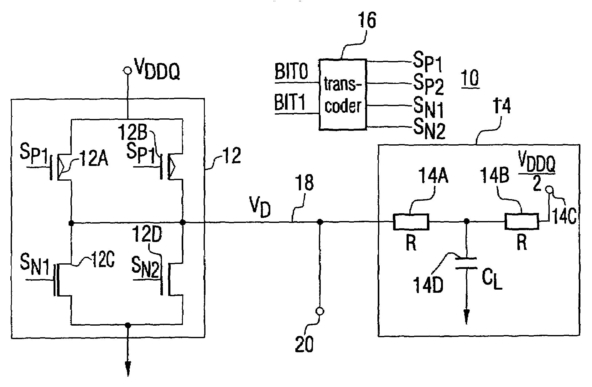
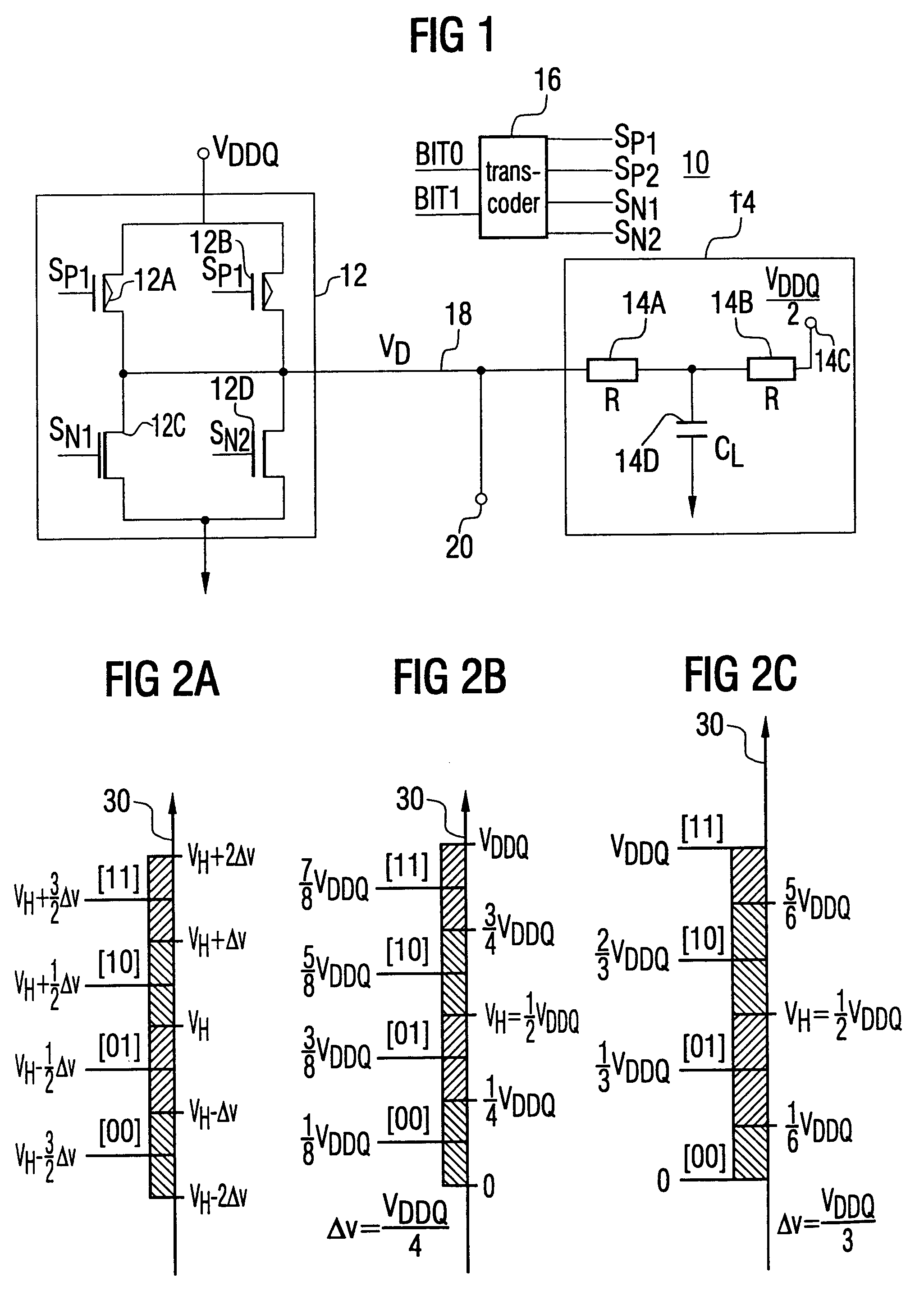
[0015]In the following, an embodiment for a driver stage will be described with reference to FIGS. 1 and 2, which may be used as a multi-level transmission interface. However, other applications are also conceivable. It is realized in MOS-technology and suited for a voltage mode driver operation and does not have to use a voltage mode driver operation. This is advantageous in that the current mode driver operation has gained great currency by the DDR-SDRAM-SSTL interface specification (DDR=double data rate; SDRAM=synchronous dynamic random access memory; SSTL=stub series terminated logic). However, the invention is not limited to the application in this interface specification. In particular, the following description relates to a four-level driver stage, with the invention, however, being also applicable to other multi-level methods with n>2.

[0016]The driver stage from FIG. 1 being generally indicated at 10, is essentially divided up into three parts, that is a push / pull circuit pa...


PUM


Abstract

An inventive driver stage for driving an output on one of n-levels, which are each spaced from each other by a voltage difference of ΔV, includes a plurality of field effect transistors for driving the output by supplying or removing a current to or from the output, with the relationship of the channel widths of at least two field effect transistors, which both function either to lead a current to or away, being set in dependence on the value of the voltage difference.

Description

BACKGROUND OF THE INVENTION[0001]1. Field of the Invention[0002]The present invention relates to driver stages for driving an output on one of n-levels, as may be used for example in multi-level signaling.[0003]2. Description of the Prior Art[0004]Multi-level signaling enjoys a growing interest with respect to bus interfaces having a high bandwidth. Multi-level signaling techniques, in which two bits are simultaneously transmitted to a clock cycle and / or a clock edge, currently take a different stand. In order to achieve this, the bus is driven to one of four different levels, which may then be decoded on the receiver-side by a simple two-bit analog / digital conversion.[0005]The U.S. Pat. No. 6,140,841 describes a high-speed interface device comprising a data driver means for decoding 2-bit data signals so as to obtain 4-level data signals, a reference voltage generation means for generating multi-level reference voltages so as to be able to differentiate between the voltage levels o...

Claims


Application Information

Patent Timeline
Patent Type & Authority Patents(United States)
IPC IPC(8): H03K19/02H03K19/00
CPCH03K19/0002
Inventor BROX, MARTIN
Owner POLARIS INNOVATIONS LTD
Why Eureka
Try Eureka