Systems and methods for correcting thermal distortion pointing errors

a technology of thermal distortion and correction methods, applied in the field of spacecraft attitude control, can solve the problems of thermal distortions having a significant impact on the design and performance of spacecraft, spacecraft cost may increase by roughly $1.6 m, and the antenna can suffer

Inactive Publication Date: 2006-05-30
LOCKHEED MARTIN CORP
View PDF5 Cites 17 Cited by
  • Summary
  • Abstract
  • Description
  • Claims
  • Application Information

AI Technical Summary

Benefits of technology

[0015]A more complete understanding of the present invention may be derived by referring to the deta

Problems solved by technology

Although this approach maintains high accuracy pointing of the attitude sensors (typically located on the spacecraft earth deck), the antenna pointing can suffer due to spacecraft structure distortions caused by temperature variations that occur as the sun orientation with respect to the spacecraft changes throughout the day and seasonally.

Method used


Image

  • Systems and methods for correcting thermal distortion pointing errors
  • Systems and methods for correcting thermal distortion pointing errors
  • Systems and methods for correcting thermal distortion pointing errors

Examples


Embodiment Construction

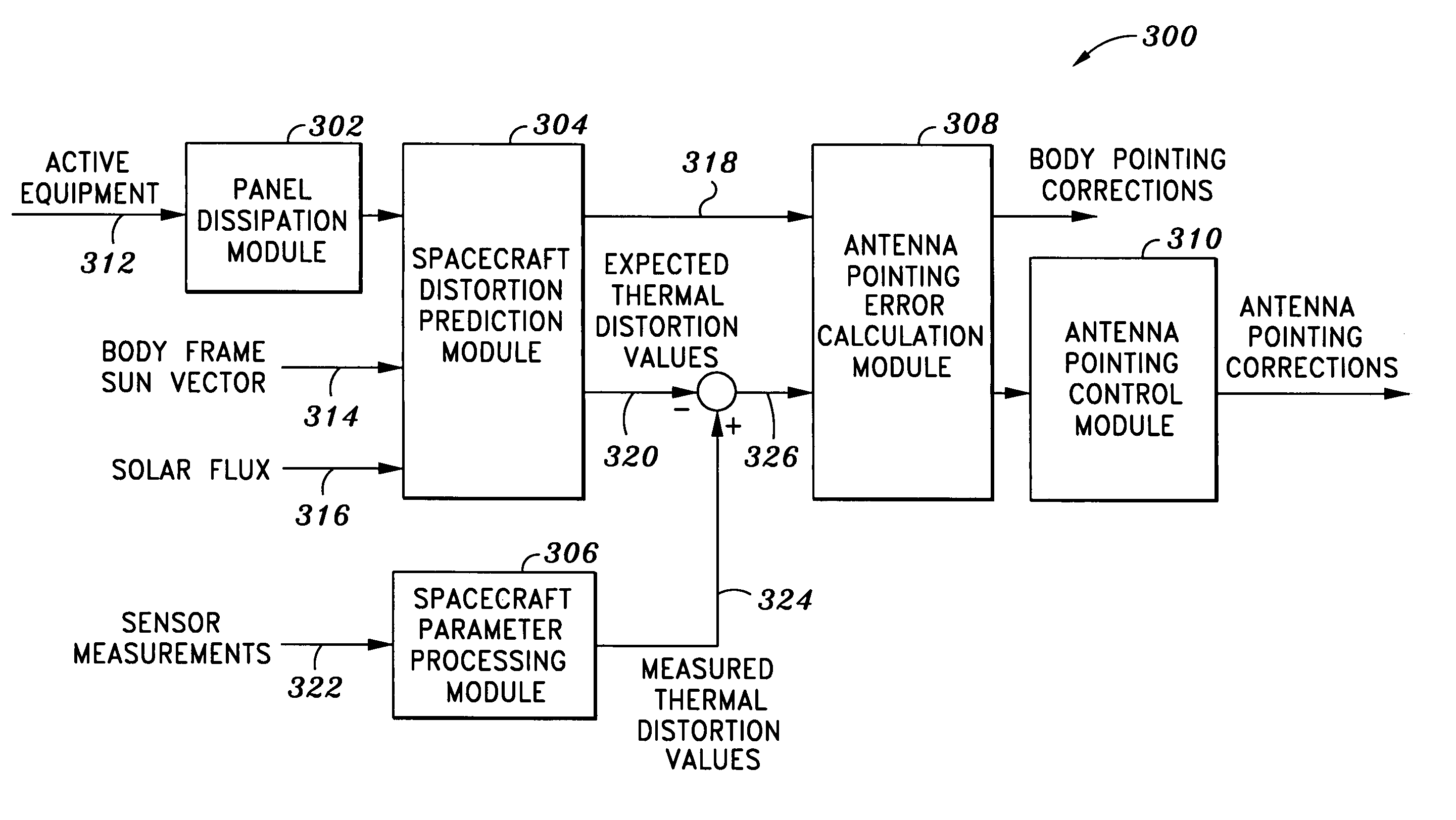
[0021]The present invention relates generally to spacecraft attitude control systems and methods, and more particularly to systems and methods for correcting spacecraft thermal distortion pointing errors. In contrast to the prior-art systems mentioned above, the present invention uses information from on-board sensors to improve the accuracy of both the distortion pointing error estimates and the antenna pointing.

[0022]In accordance with one embodiment of the invention, measurements from on-board strain gages are used to sense local distortions at certain positions on the spacecraft structure. An antenna pointing error prediction and correction system uses the differences between the strain gage measurements and predicted local distortions obtained using a spacecraft distortion model to update the antenna pointing error estimates. Spacecraft pointing and antenna gimbal positions then are changed to null the thermal distortion pointing errors. In accordance with another embodiment of...


PUM


Abstract

One embodiment of the present invention relates to a system for correcting spacecraft thermal distortion pointing errors. The system comprises one or more spacecraft sensors located at positions on a spacecraft and which are adapted to measure spacecraft parameters at those positions. The system also includes a spacecraft distortion prediction module, which is adapted to generate expected spacecraft thermal distortion parameter values and expected antenna thermal distortion pointing errors. Further, the system includes a spacecraft parameter processing module adapted to generate measured spacecraft thermal distortion parameter values from the measured spacecraft parameters, and an antenna pointing error calculation module adapted to calculate antenna pointing error correction commands. Finally, the system includes an antenna pointing control module adapted to receive the antenna pointing correction commands and control the adjustment of the antenna pointing using the correction commands.

Description

BACKGROUND OF THE INVENTION[0001]The present invention relates generally to spacecraft attitude control, and more particularly to systems and methods for correcting spacecraft thermal distortion pointing errors.[0002]FIG. 1 is a drawing of one embodiment of a communications spacecraft 100, having a plurality of communications antennas 102–108 mounted on the east and west sides of the spacecraft and on the earth deck. To perform its mission, the spacecraft must maintain the payload antennas pointing at their earth coverage regions at all times. As one skilled in the art will appreciate, this is accomplished using an attitude control system that senses the spacecraft attitude using attitude sensors, such as earth sensors, sun sensors, star sensors, gyros and the like, and applies control torques using reaction wheels or thrusters to null the attitude errors. Although this approach maintains high accuracy pointing of the attitude sensors (typically located on the spacecraft earth deck)...

Claims


Application Information

Patent Timeline
IPC IPC(8): H01Q3/00
CPCH01Q3/26
Inventor GOODZEIT, NEIL EVANRATAN, SANTOSHMCKINNON, DOUGLAS VERNON
Owner LOCKHEED MARTIN CORP
Why Eureka
Try Eureka