
Helicopter Sling-Load Stability Control and Release System

a technology of stability control and helicopter sling, applied in process and machine control, instruments, navigation instruments, etc., can solve problems such as aircraft uncontrollable, load stability during flight, and long tethers

Active Publication Date: 2013-02-28
TOLLENAERE DONALD JOHN +1
View PDF1 Cites 131 Cited by
  • Summary
  • Abstract
  • Description
  • Claims
  • Application Information

AI Technical Summary

Benefits of technology

The present invention is a computer-operated hook assembly for helicopters or UAVs that enables automatic pick-up and delivery of sling loads. The hook assembly is a self-contained and portable device that can be easily moved from aircraft to aircraft or UAVs with minimal modification. It uses sensors and a GPS unit to direct navigation and control load stability during transport. The hook assembly provides real-time data on load orientation and relative acceleration, which is transmitted to the aircraft's navigation and control systems for safe and smooth operation. The hook assembly can also receive mission data remotely or locally and is designed to interface with existing aircraft instruments for load control and monitoring. The technical effects of the invention include increased operational efficiency, safety, and mobility of hook assembly operations.

Problems solved by technology

Further, long tethers keep the aircraft away from terrain obstacles and rotor-induced visibility problems, such as dust brown-outs or snow white-outs.
However, certain problems occur with long tethers.
First is the problem of load stability during flight.
Such a condition will make the aircraft uncontrollable.
Additional hazards occur when pick-up and attachment times are lengthy thereby exposing the aircraft to hostile fire and endangering ground crew members.
Similarly, during delivery and release, delays and ground crew actions can expose both aircraft and ground crew to hostile action.

Method used


Image

  • Helicopter Sling-Load Stability Control and Release System
  • Helicopter Sling-Load Stability Control and Release System
  • Helicopter Sling-Load Stability Control and Release System

Examples


Embodiment Construction

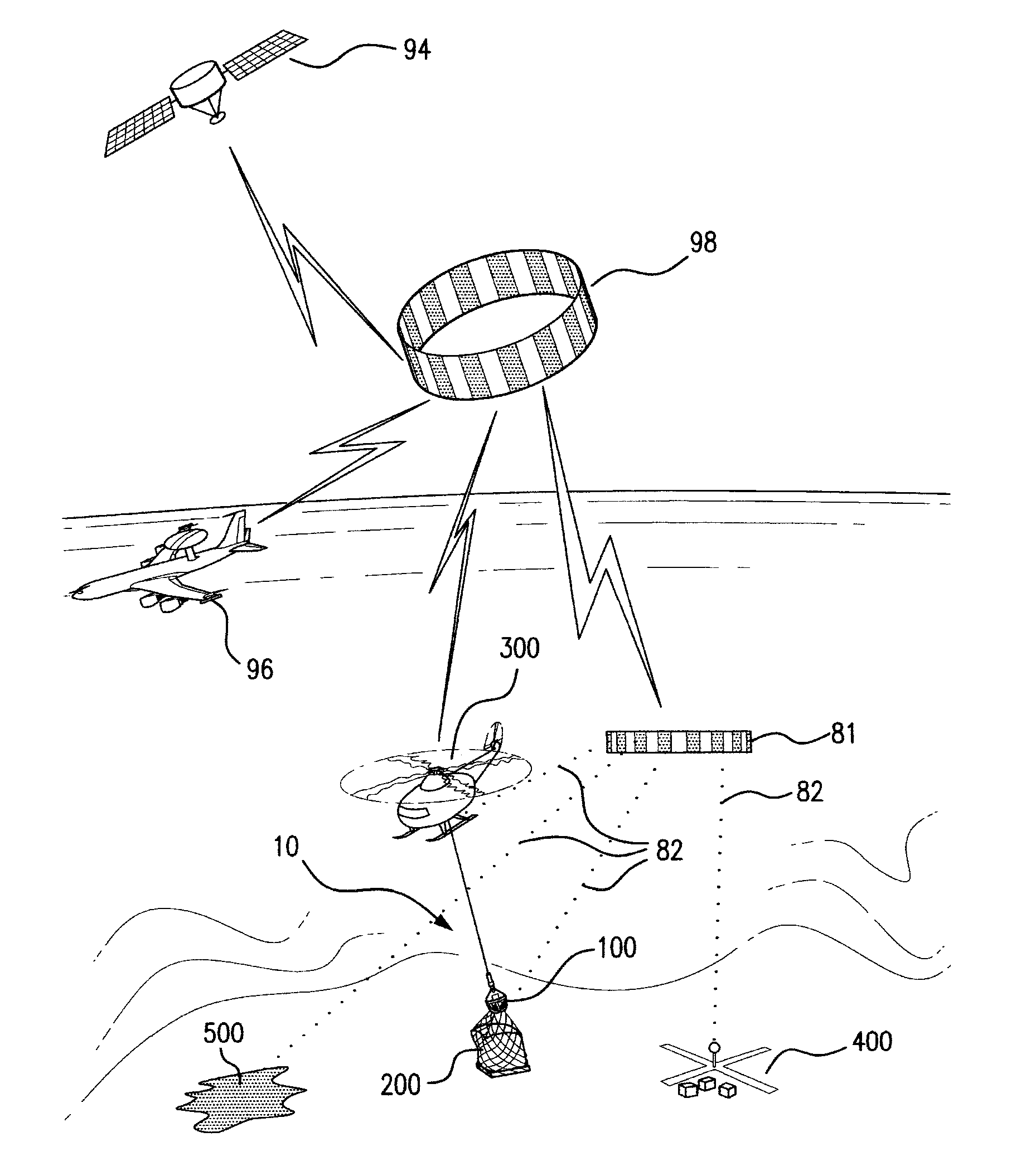
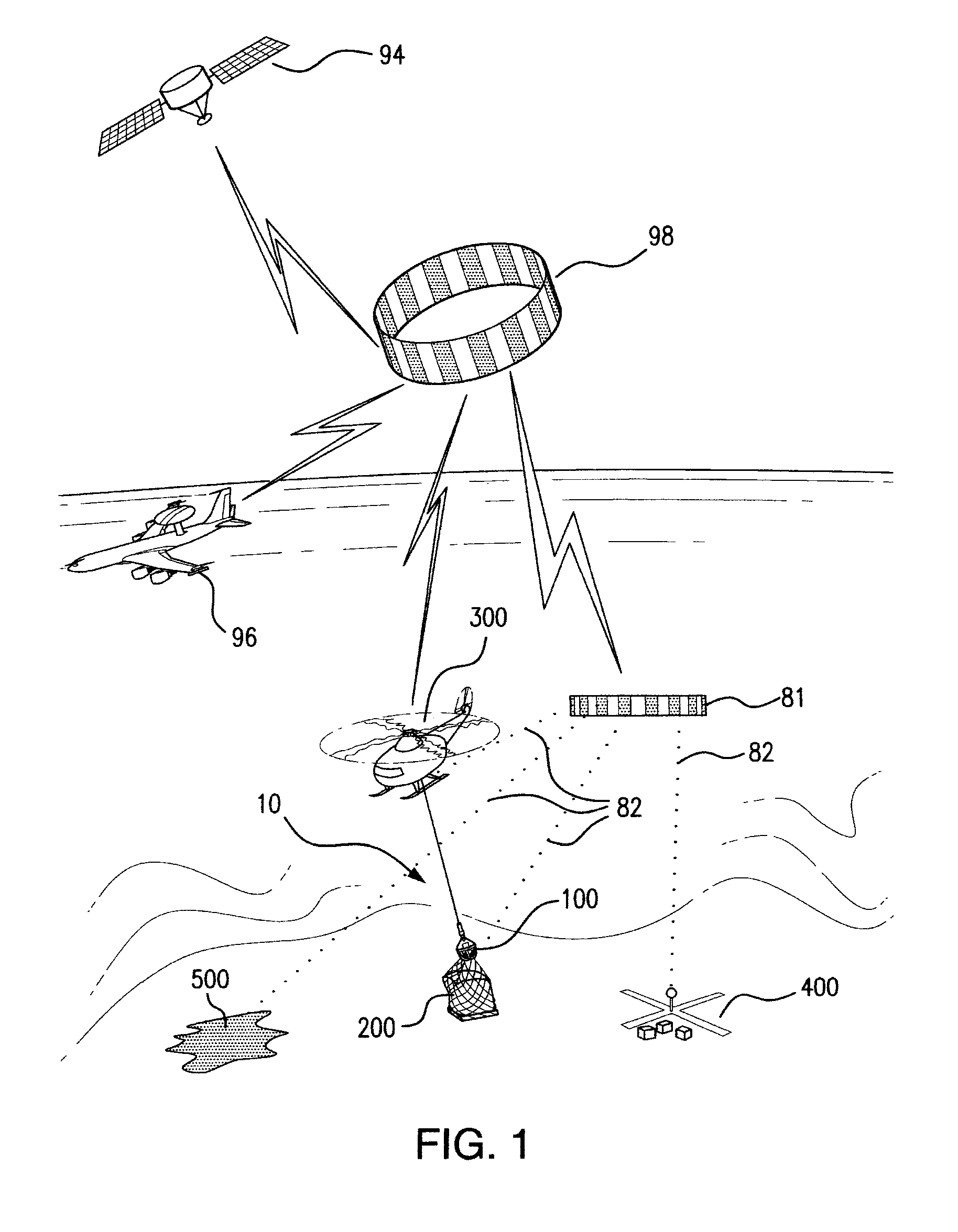
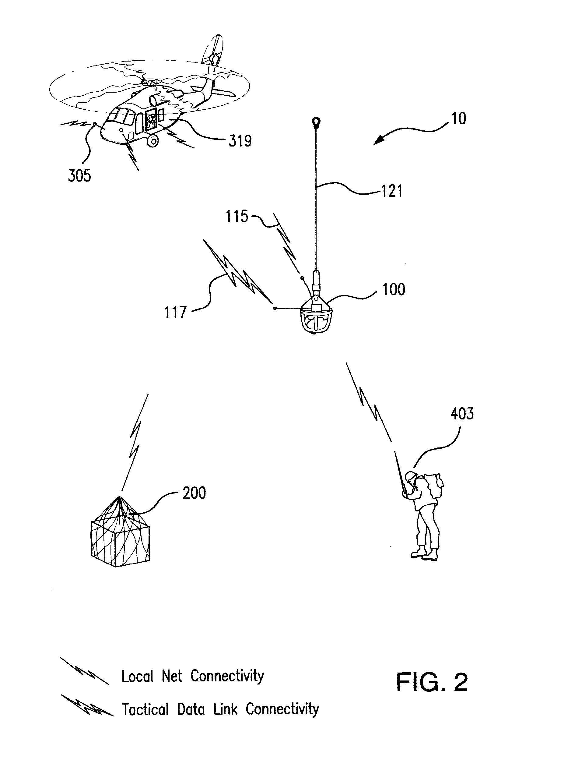
[0028]Referring now to FIG. 1, the helicopter sling load control system of the present invention, designated generally by the reference numeral 10, is shown in a representative operational network. The sling load control system comprises the sling line extending from the aircraft, the hook assembly which provides mission control and communications, and remote server clients located on the aircraft, the load, and the pickup and drop points. The hook assembly 100 communicates with the various clients using local data net 81 notionally represented with wireless connections 82 to the aircraft 300, load 200, pick up point 400, and drop point 500. Local data net 81 is formed by the server computer contained within hook assembly 100 in conjunction with the server clients, such as the aircraft 300 and the load 200 itself. The local data net 81, a short range system such as a WiMAX net, may not be in contact with all clients simultaneously. For example, the hook assembly can be in wireless c...


PUM


Abstract

A sling load computer-operated hook assembly for helicopter or unmanned aerial vehicle (UAV) use is provided. The hook assembly allows automated pick-up and delivery. The computer hook assembly also (1) directs navigation of the aircraft, (2) finds and engages loads for pickup, (3) controls stability of the sling load enroute, and (4) releases the load at the delivery point. The self-contained feature allows the hook assembly to be moved from aircraft to aircraft. The hook assembly senses weight, motion and position of the load for stability control. An integral GPS unit is used to direct navigation. These data are transmitted to the aircraft autopilot and flight director instruments to provide navigation to the designated points and to control load stability enroute. Mission data for pick-up and release points can be received remotely from a command and control tactical data net. Alternately, mission data can be locally entered.

Description

FEDERALLY SPONSORED RESEARCH OR DEVELOPMENT[0001]Not ApplicableFIELD OF THE INVENTION[0002]The present invention relates to helicopter sling-loads and more particularly to automating payload stability control and payload pick-up, delivery, and release.BACKGROUND OF THE INVENTION[0003]Delivery and pick-up of payloads by helicopter slings allow the aircraft to remain airborne with no landing zone required and also allow the carriage of outsized equipment. Further, long tethers keep the aircraft away from terrain obstacles and rotor-induced visibility problems, such as dust brown-outs or snow white-outs. However, certain problems occur with long tethers. First is the problem of load stability during flight. A long tether can allow a load to oscillate or simply move to a point where the center-of-gravity limits of the aircraft are exceeded. Such a condition will make the aircraft uncontrollable.[0004]Additional hazards occur when pick-up and attachment times are lengthy thereby exposing...

Claims


Application Information

Patent Timeline
Patent Type & Authority Applications(United States)
IPC IPC(8): B64D1/22B64C19/00
CPCB64D1/22G05D1/0858
Inventor TOLLENAERE, DONALD JOHNSMITH, TIMOTHY EDWARD
Owner TOLLENAERE DONALD JOHN
Learn More