Systems and methods for deployment and operation of unmanned aerial vehicles

a technology for unmanned aerial vehicles and systems, applied in the field of unmanned aerial vehicle systems, can solve the problems of unpractical uav operations, large logistics requirements, and inability to achieve desired uav operations, and achieve the effects of improving launch reliability, long shelf life, and low cos

Inactive Publication Date: 2013-05-14
SEACORP LLC
View PDF54 Cites 130 Cited by
  • Summary
  • Abstract
  • Description
  • Claims
  • Application Information

AI Technical Summary

Benefits of technology

[0014]In an embodiment, UAV launch can be accomplished using an inflator-based impulse mechanism. Using such a system, launch reliability can be enhanced over known systems by the replacement of current launcher systems with, for example, commercially available gas generators, such as automotive air bag gas generators or cold gas inflators, that can provide the impulse energy to launch a UAV from a tube. Commercially available inflators, typically with a long shelf life, can be relatively inexpensive, reliable and permit the modularity of a sealed and relatively maintenance-free launcher system. Through inflator selection and variable timing, for example, this technology can be adapted to a variety of UAV platforms.
[0015]An inflator-based impulse mechanism can reduce the logistics requirements of the remote standalone UAV system, e.g., no need for air compressors or large compressed air storage tanks or external power. The inflator technology can provide a payload launcher that is very modular, requires little or no maintenance and can be nearly 100% operationally ready at all times. Because of the versatility of the inflators, various UAV types, with different characteristics, can be accommodated within a single launcher. Because the system is mostly self-contained, it can be used aboard most any platform such as ground vehicles or sea going vessels and can be installed, removed or modified quickly for mission-specific payloads.
[0017]In an embodiment, the system can use solar or wind power to generate electricity to eliminate the need for an external power supply.
[0018]In an embodiment, access to the launcher area can be secured to prevent tampering of the unattended system, e.g., the launchers and UAVs. Components of the system can be constructed of steel or other suitable material to prevent damage from small arms fire, for example. Additionally, the system can include local security monitoring features as part of a security subsystem. For example, the tower area can have motion sensors and a camera system suitable for daytime and nighttime monitoring of the area around the UAV system. In an embodiment, when a motion sensor is triggered by a possible intruder, the camera system can be automatically activated and can be controlled from a remote station such that live streaming video of the area around the UAV system can be viewed from a remote location.

Problems solved by technology

Additionally, known UAV deployment and operation systems, such as disclosed in U.S. Pat. No. 7,089,843 to Miller et al., can require extensive logistics.
In some locations, the personnel and logistics requirements may make desired UAV operations impractical.

Method used


Image

  • Systems and methods for deployment and operation of unmanned aerial vehicles
  • Systems and methods for deployment and operation of unmanned aerial vehicles
  • Systems and methods for deployment and operation of unmanned aerial vehicles

Examples


Embodiment Construction

[0027]To facilitate an understanding of the principles upon which the subject matter disclosed herein is based, most illustrative embodiments are described hereinafter with reference to their implementation at a remote, land-based site. It will be appreciated that the practical applications of these principles are not limited to this particular type of implementation. Rather, they can be equally employed in any other type of UAV system operating environment where it is desired to provide for periods of deployment and operation with reduced personnel and logistics requirements.

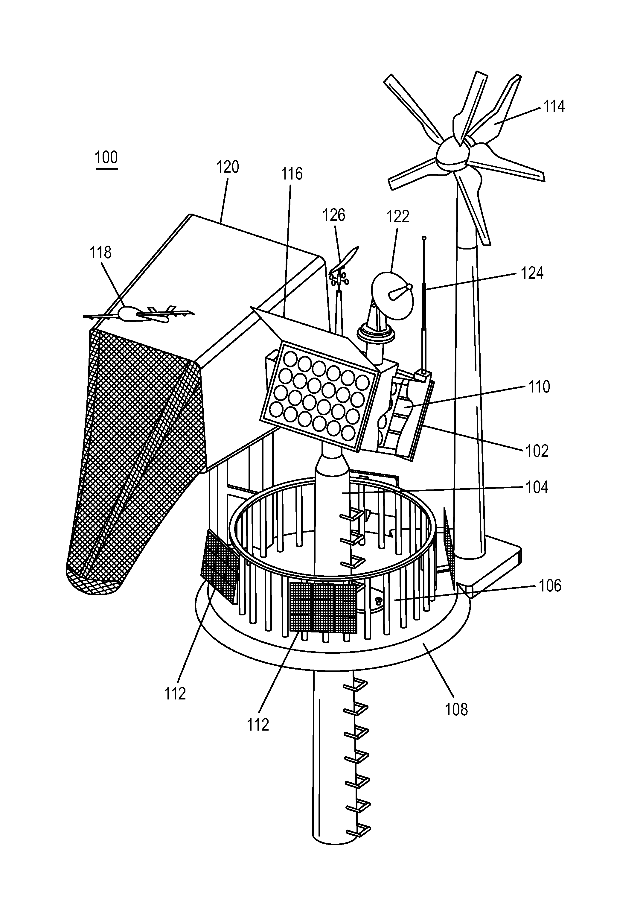
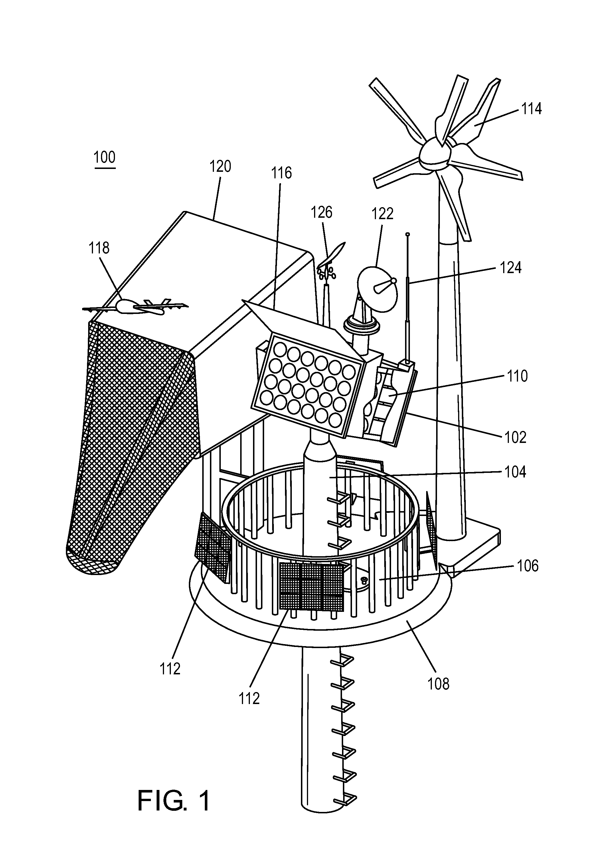
[0028]FIG. 1 shows an illustrative embodiment of UAV system 100. In an embodiment, UAV system 100 can include a launcher 102, hereinafter referred to as a Launch Tube Cluster (LTC), comprising one or more launch tubes (LTs) 110 configured to house UAVs in a UAV canister (UC) (not shown in FIG. 1). In an embodiment, a 24-tube LTC 102 can be mounted on a fixed support structure, such as tower 104. Tower 104 conta...


PUM


Abstract

An unmanned aerial vehicle (UAV) system provides for UAV deployment and remote, unattended operation with reduced logistics requirements. The system includes a launcher that can include one or more launch tubes, each launch tube configured to house a UAV in a canister and one or more gas generators operatively connected to each canister and configured to push the UAV out of the launch tube by releasing gas into the canister. A controller for activating the gas generators can sequentially, and with a predetermined time delay, expel the UAV with a desired velocity and acceleration. The system further includes a UAV recovery device, a power supply, a security subsystem, a command and control subsystem and a communications subsystem. Command, control and communications can be provided between a remote station and the UAV.

Description

CROSS-REFERENCE TO RELATED APPLICATIONS[0001]This application claims priority from U.S. Provisional Patent Application Ser. No. 61 / 508,926, filed Jul. 18, 2011, the disclosure of which is hereby incorporated by reference in its entirety.STATEMENT REGARDING FEDERALLY SPONSORED RESEARCH OR DEVELOPMENT[0002]Not Applicable.BACKGROUND[0003]1. Field[0004]The disclosed subject matter is generally directed to unmanned aerial vehicle (UAV) systems, and more particularly, to systems and methods that provide for the deployment and remote operation of UAVs in, for example, reconnaissance operations.[0005]2. Description of Related Art[0006]Known UAVs can be defined as powered aerial vehicles that do not carry a human operator, use aerodynamic forces to provide vehicle lift, can fly autonomously or be piloted remotely, can be expendable or recoverable, and can carry a lethal or nonlethal payload.[0007]There can be a wide variety of UAV shapes, sizes, configurations, and characteristics. For examp...

Claims


Application Information

Patent Timeline
Patent Type & Authority Patents(United States)
IPC IPC(8): B64F1/04
CPCB64F1/02B64F1/04B64C39/024B64C2201/084B64C2201/182B64C2201/205B64C2201/208B64F1/0297B64F1/027B64U70/70B64U70/30B64U80/84B64U80/86
Inventor LUSSIER, DAVID A.DELISLE, ANDREW J.TORRENCE, PHILIP M.
Owner SEACORP LLC
Why Eureka
Try Eureka