
Method and camera system for blurring portions of a verification image to show out of focus areas in a captured archival image

a camera system and verification image technology, applied in the field of electronic imaging, can solve the problems of difficult to determine the sharpness of the captured image, the user may not be able to determine, and the decrease in sharpness may not be readily apparen

Inactive Publication Date: 2006-05-30
INTELLECTUAL VENTURES FUND 83 LLC
View PDF49 Cites 56 Cited by
  • Summary
  • Abstract
  • Description
  • Claims
  • Application Information

AI Technical Summary

Benefits of technology

"The present invention provides a method and camera system for effectively determining which parts of an archival image are out of focus and displaying a verification image that shows the out of focus areas as blurred when presented on an electronic display. This technology can be used to improve the quality of archival images and make them easier to view and analyze."

Problems solved by technology

However, since in many cameras the user is not seeing the scene through the archival optical system, it is not possible for the user to determine whether the captured image is focused at the correct depth, and therefore, on the correct subject.
One drawback of the use of verifying cameras is that most displays currently in use with such cameras are relatively small, thus making it difficult to determine the sharpness of the captured image.
This is a particular problem when the verifying camera includes a so called “digital zoom” or “pseudo zoom” capability.
However, this decrease in sharpness may not be readily apparent in the verification image that is presented on the display.
This in turn can cause the user to make incorrect decisions regarding whether to capture an additional image of the scene.

Method used


Image

  • Method and camera system for blurring portions of a verification image to show out of focus areas in a captured archival image
  • Method and camera system for blurring portions of a verification image to show out of focus areas in a captured archival image
  • Method and camera system for blurring portions of a verification image to show out of focus areas in a captured archival image

Examples


first embodiment

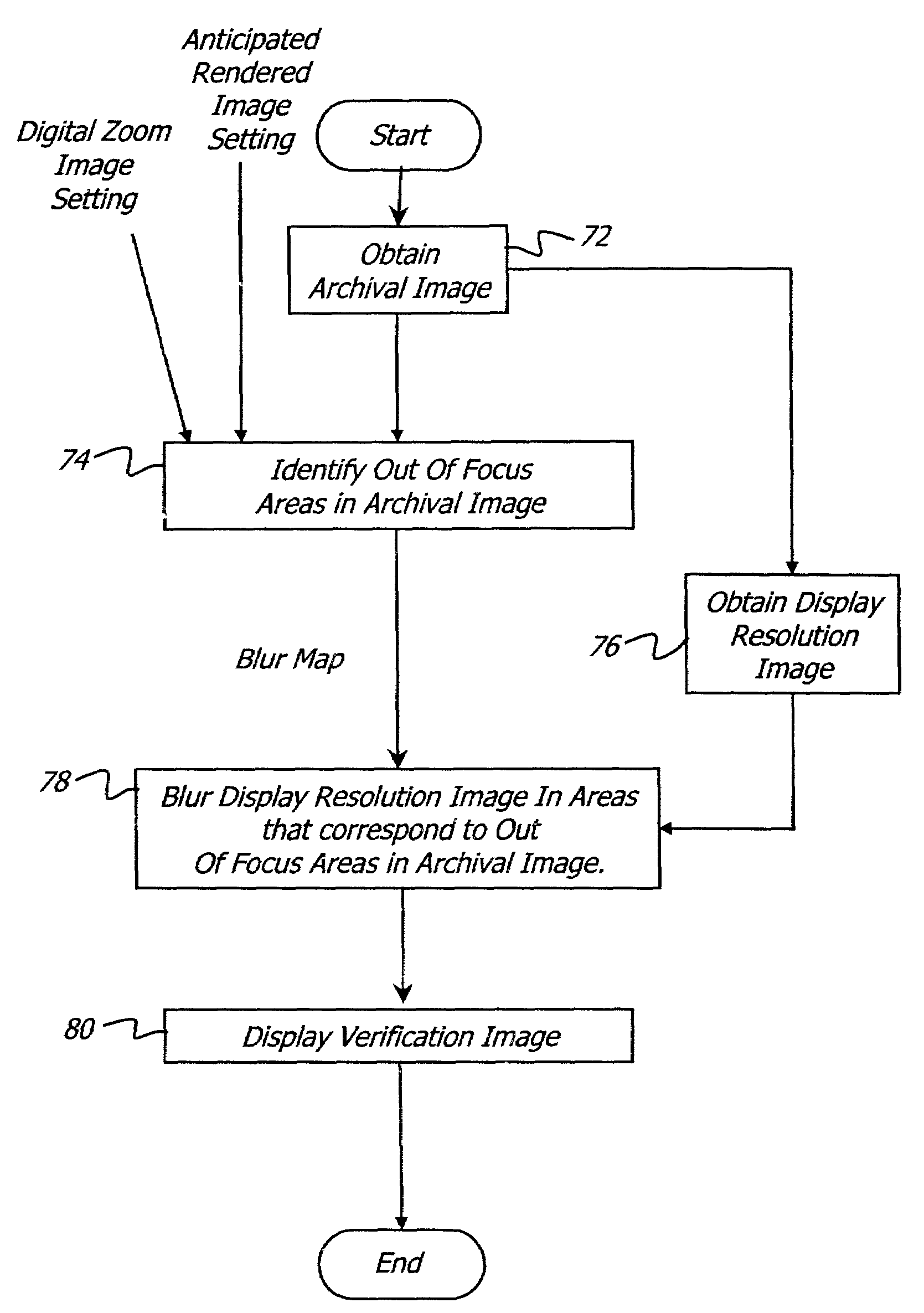
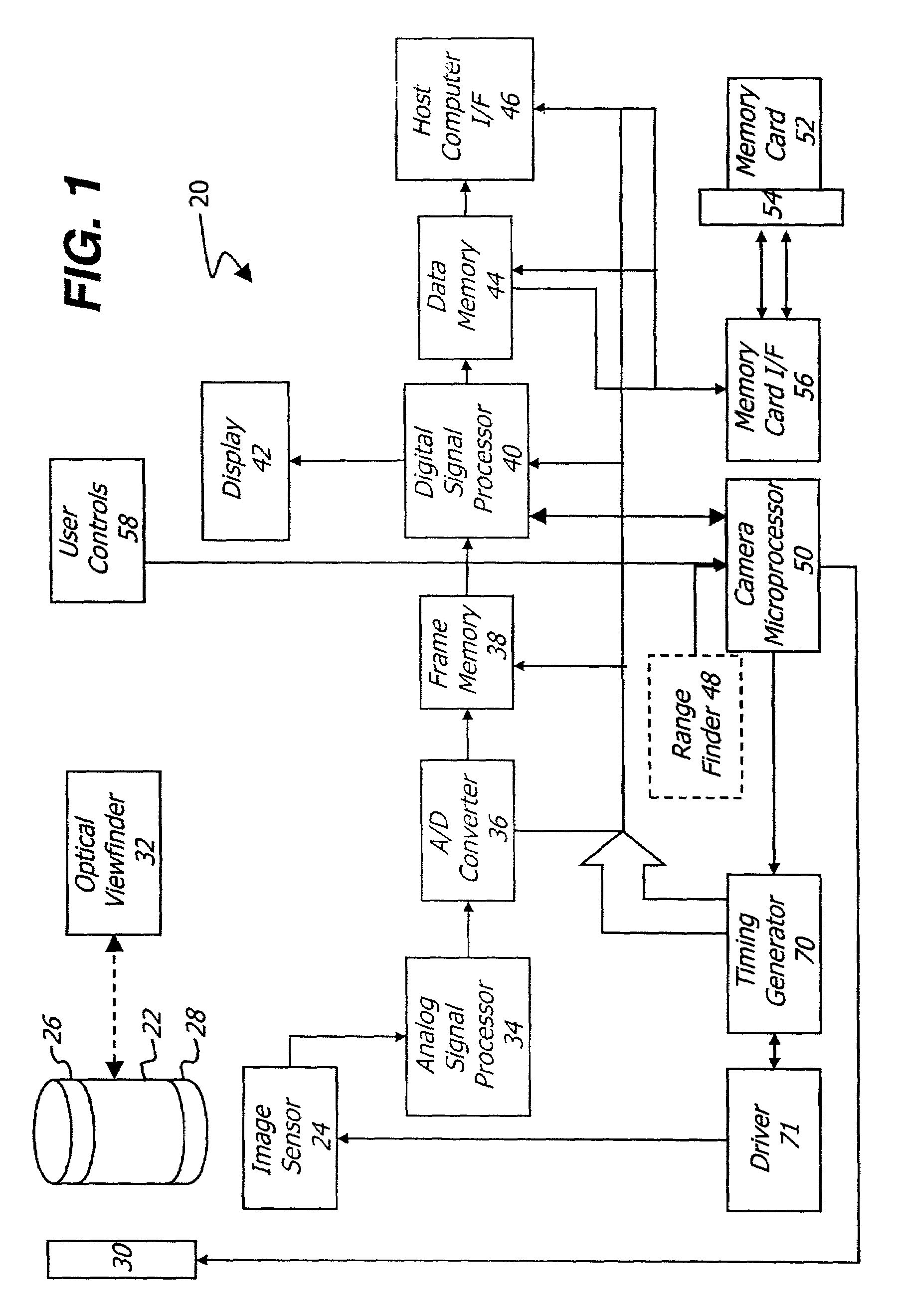
[0064]FIG. 3a shows a flow diagram depicting the method of the present invention. This method can be performed by the digital signal processor 40 in camera 20. As is shown, an archival image is obtained (block 72). Typically, this step will be accomplished by image capture using image sensor 24 as described above. The captured archival image is processed as described earlier and resampled to provide the appropriate digital zoom level. However, the archival image may also be obtained from a memory such as memory 38 and memory card 52 or other memory device (not shown) through host computer interface 46.

[0065]The areas of the archival image that are out of focus are then identified (block 74) in a “blur map” that is created in a manner that will be described later. The archival image is resampled in order to provide a display resolution verification image (block 46). If the digital zoom setting is 1:1 (e.g. no resampling), a normal level of low pass filtering, to minimize aliasing, is...

second embodiment

[0066]FIG. 3b shows a flow diagram depicting the method of the present invention. As described in relation to FIG. 3a, an archival image is obtained (block 82), and the areas of the archival image that are out of focus are then identified (block 84) by providing a blur map. The archival image is adaptively resampled in order to provide a verification image (block 86). The adaptive resampling provides a variable level of low pass filtering, which is a function of both the digital zoom setting and the blur map values. As the digital zoom level increases, or the blur map values increase, and the low pass filtering provided prior to resampling is modified to provide more blurring, so that this particular region of the verification image includes significant blurring. Optionally, the display resolution image is then overlaid with an icon or text message 68 indicating that the image quality is not at the peak level, when significant levels of digital zoom are used in capturing the archiva...


PUM


Abstract

In one aspect of the present invention, a method is provided for using a display having a predetermined display resolution to show out of focus areas in an archival image having a greater resolution than the predetermined display resolution. In this method, a verification image sized for presentation on the display, is provided. Portions of the archival image that are out of focus are identified. The verification image is blurred so that portions of the verification image that correspond to out of focus portions of the archival image appear out of focus when the verification image is presented on the display.In another aspect a camera system is provided having a source of an archival image with a predetermined resolution and a verification display having an image display resolution that is lower than the predetermined resolution of the archival image. A signal processor is provided, with said signal processor processing the archival image to identify out of focus portions of the archival image and to form a verification image formatted for presentation on the verification display said signal processor further modifying the appearance of the verification image so that portions of the verification image that correlate to identified portions of the archival image appear out of focus when the modified verification image is presented on the verification display.

Description

CROSS REFERENCE TO RELATED APPLICATIONS[0001]Cross reference is made to related application Ser. No. 09 / 176,805 filed Oct. 22, 1998.FIELD OF THE INVENTION[0002]The present invention relates generally to the field of electronic imaging, and in particular, a verifying camera system that visibly blurs portions of a verification image that correspond to portions of an archival image which are out of focus.BACKGROUND OF THE INVENTION[0003]Many camera systems capture archival images using an optical system containing an automatic focus lens with a limited depth of focus. In these systems, the user generally centers the subject in the viewfinder and the camera lens autofocus control algorithm moves the lens focus position based on the sharpness of the subject either at a single spot or in multiple zones. Some cameras alternatively use a distance measure feedback from a discrete sensor to set a focus position. However, since in many cameras the user is not seeing the scene through the archi...

Claims


Application Information

Patent Timeline
Patent Type & Authority Patents(United States)
IPC IPC(8): H04N5/232G03B13/00
CPCH04N1/0044H04N5/23293H04N5/23212G03B2217/005H04N2201/325H04N23/959H04N23/634H04N23/635
Inventor BELZ, STEVEN M.ADAMS, JAMES E.PARULSKI, KENNETH A.
Owner INTELLECTUAL VENTURES FUND 83 LLC
Learn More