Power-mode controlled power converter

a power converter and power mode technology, applied in the field of power converters, can solve the problems of skewing the accuracy the size and device count of the power converter, and the optical-coupler and other secondary-side control circuitry, and achieve the effect of high impedan

Active Publication Date: 2006-05-30
SEMICON COMPONENTS IND LLC
View PDF9 Cites 96 Cited by
  • Summary
  • Abstract
  • Description
  • Claims
  • Application Information

AI Technical Summary

Problems solved by technology

However, the optical-coupler and other secondary-side control circuitry add significantly to the size and device count of the power converter.
This is a main drawback of this power converter.
However, any of several factors can skew the accuracy of this method.
Furthermore, the propagation delay time TD affects the precision of the output current IO.
According to foregoing description, we can find that the primary-side control of the prior art is not accurate and is not fit for the mass production of the power converter.

Method used


Image

  • Power-mode controlled power converter
  • Power-mode controlled power converter
  • Power-mode controlled power converter

Examples


Embodiment Construction

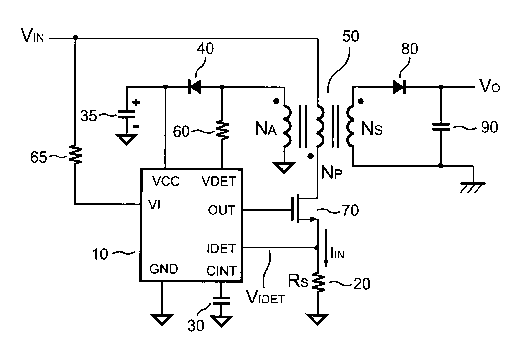
[0042]FIG. 5 shows a power-mode controlled power converter according to the present invention. The power-mode controlled power converter according to the present invention includes a PWM controller 10 having a supply terminal VCC, a voltage-detection terminal VDET, a line-voltage input terminal VI, a filter terminal CINT, a current-detection terminal IDET, an output terminal OUT, and a ground terminal GND. The power-mode controlled power converter according to the present invention also includes a line resistor 65, a decouple capacitor 35, an auxiliary rectifier 40, a detection resistor 60, an integrate-capacitor 30, a sense resistor 20, a power transistor 70, an output rectifier 80, and an output capacitor 90. The power-mode controlled power converter of the present invention further includes a transformer 50 having an auxiliary winding NA, a primary winding NP, and a secondary winding NS.

[0043]A first terminal of the line resistor 65 is supplied with an input voltage VIN of the po...


PUM


Abstract

A power-mode controlled power converter is capable of supplying a constant output voltage and output current. A PWM controller generates a PWM signal in response to a voltage sampled from a transformer auxiliary winding. A programmable current-sink and a detection resistor compensate for a voltage drop of an output rectifier. A low-pass filter integrates a switching-current voltage to an average-current signal. An attenuator produces an input-voltage signal from a line-voltage input signal. The PWM controller multiplies the average-current signal with the input-voltage signal to generate a power-control signal. An error-amplifier compares the power-control signal with a power-reference voltage to generate a limit voltage. The limit voltage controls the power delivered from a primary-side circuit to a secondary-side circuit of the power-mode controlled power converter. Since the power-reference voltage varies in proportional to output voltage variations, a constant output current is therefore achieved.

Description

BACKGROUND OF THE INVENTION[0001]1. Field of the Invention[0002]The present invention relates to a power converter and more specifically relates to a primary-side controlled power converter.[0003]2. Description of Related Art[0004]Various modes of control for power converters have been widely used to regulate an output voltage and an output current. Two common modes for such regulation are voltage-mode and current-mode.[0005]FIG. 1 shows a traditional power converter. An error amplifier 12 and an error amplifier 13 are utilized to produce a feedback signal from the output current and the output voltage. The feedback signal will be provided to a PWM controller 11 in the primary-side circuit via an optical-coupler 14. The PWM controller 11 generates a PWM signal to switch a transformer 51 by switching a transistor 70. A switching current flowing through the transistor 70 is converted to a detection voltage signal via a resistor 20. The PWM controller 11 compares the feedback signal wi...

Claims


Application Information

Patent Timeline
Patent Type & Authority Patents(United States)
IPC IPC(8): H02M3/335
CPCH02M3/33507H01F2038/026
Inventor YANG, TA-YUNGCHEN, CHERN-LINLIN, JENN-YU G.HUNG, GUO-KIANG
Owner SEMICON COMPONENTS IND LLC
Why Eureka
Try Eureka