Multi-rate shared memory architecture for frame storage and switching

a shared memory and frame storage technology, applied in the field of fibre channel switching technology, can solve the problems of inefficiency of existing buffer architectures and memory was

Active Publication Date: 2006-05-30
AVAGO TECH INT SALES PTE LTD
View PDF13 Cites 2 Cited by
  • Summary
  • Abstract
  • Description
  • Claims
  • Application Information

AI Technical Summary

Benefits of technology

[0008]A shared memory design in accordance with the present invention provides a solution to the aforementioned problem by providing a shared location for storing data frames prior to transmission to a receiving port in an effici

Problems solved by technology

Existing architectures for buffer are also inefficient.
Buffers must handle both rate adaptive cases

Method used


Image

  • Multi-rate shared memory architecture for frame storage and switching
  • Multi-rate shared memory architecture for frame storage and switching
  • Multi-rate shared memory architecture for frame storage and switching

Examples


Embodiment Construction

[0026]The present invention is illustrated and described in terms of a fibre channel fabric and particular fibre channel fabric elements (e.g., switches), however, the present invention is readily adapted to other protocols and environments. Particular examples herein specify data transmission rates and specific values and types of components to ease illustration and understanding. However, these specific examples are not limitations of the present invention unless explicitly indicted to the contrary.

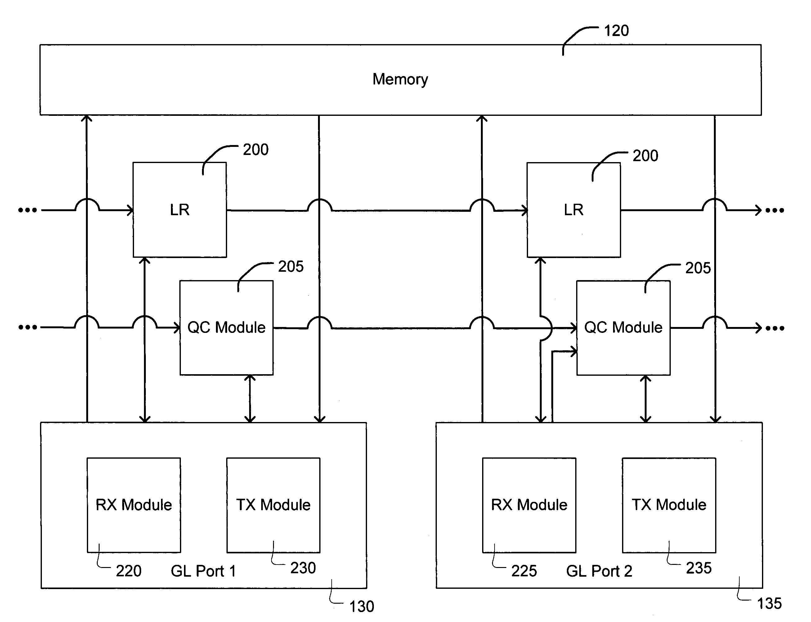
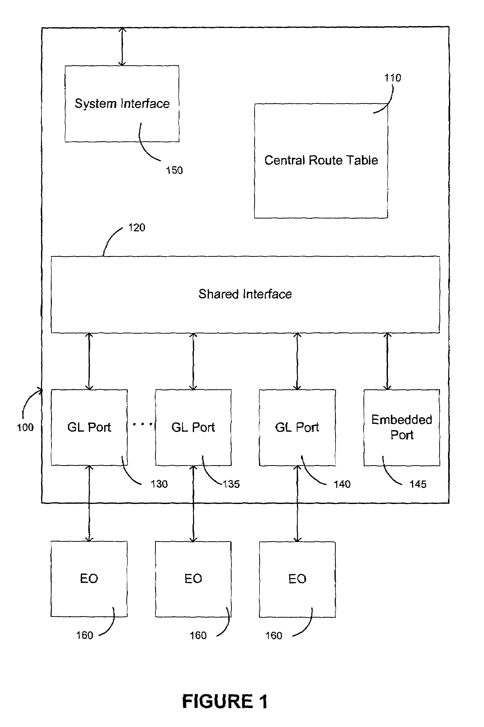
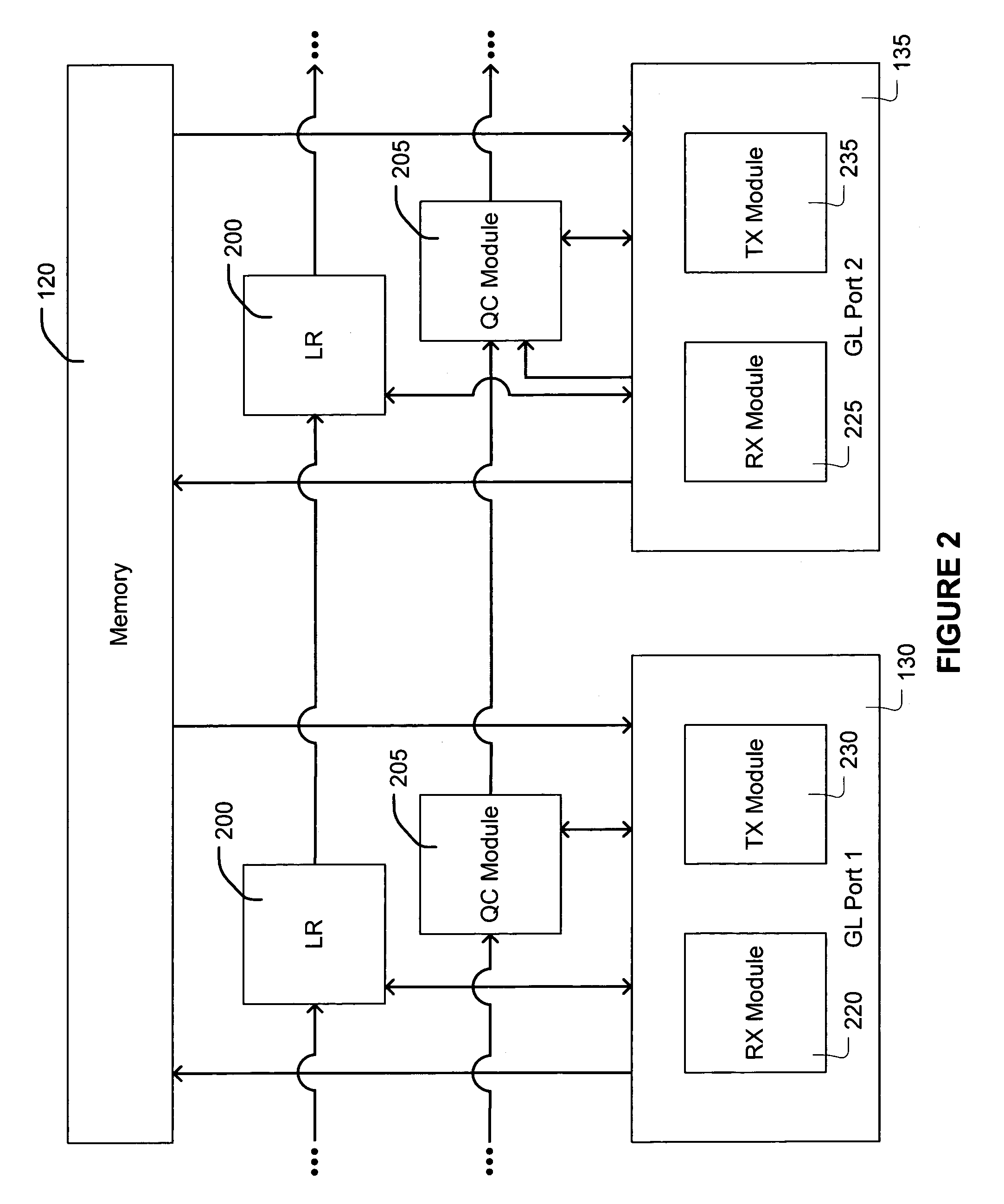
[0027]FIG. 1 shows a generalized block diagram of a fibre channel switch for use in a fibre channel fabric implementing the method and systems of the present invention. In one embodiment, the fibre channel switching element 100 of FIG. 1 may be implemented on a single application specific integrated circuit (ASIC). However, there are many implementations of switch 100 not shown, such as frame buffer memory could be located in each GL_Port in which case shared memory is replicated with a...


PUM


Abstract

Shared memory provides buffering and switching for all frames that flow through a fiber channel switch. Received frames are written to shared memory by the receiving port then read from shared memory by the transmitting port. Shared memory provides for data to be written to a buffer at one rate, and read from a buffer at a different rate, or vice versa.

Description

BACKGROUND OF THE INVENTION[0001]The present invention relates, in general, to the field of fibre channel switching technology. More particularly, the present invention relates to a route caching scheme for a receive port in a fibre channel switch.[0002]Fibre Channel is a high performance, serial interconnect standard designed for bi-directional, point-to-point communications between servers, storage systems, workstations, switches, and hubs. It offers a variety of benefits over other link-level protocols, including efficiency and high performance, scalability, simplicity, ease of use and installation, and support for popular high level protocols.[0003]Fibre channel employs a topology known as a “fabric” to establish connections between ports. A fabric is a network of switches for interconnecting a plurality of devices without restriction as to the manner in which the switch can be arranged. A fabric can include a mixture of point-to-point and arbitrated loop topologies.[0004]In Fib...

Claims


Application Information

Patent Timeline
IPC IPC(8): H04L12/50G06F13/00G06F13/14G06F13/16G06F13/36G06F13/40H04L12/56
CPCG06F13/1689G06F13/4022H04L49/357H04L49/254H04L49/103
Inventor MITCHEM, WILLIAM J.
Owner AVAGO TECH INT SALES PTE LTD
Why Eureka
Try Eureka