Method and apparatus for assigning bit metrics for soft decision decoding
- Summary
- Abstract
- Description
- Claims
- Application Information
AI Technical Summary
Problems solved by technology
Method used
Image

Examples
first embodiment
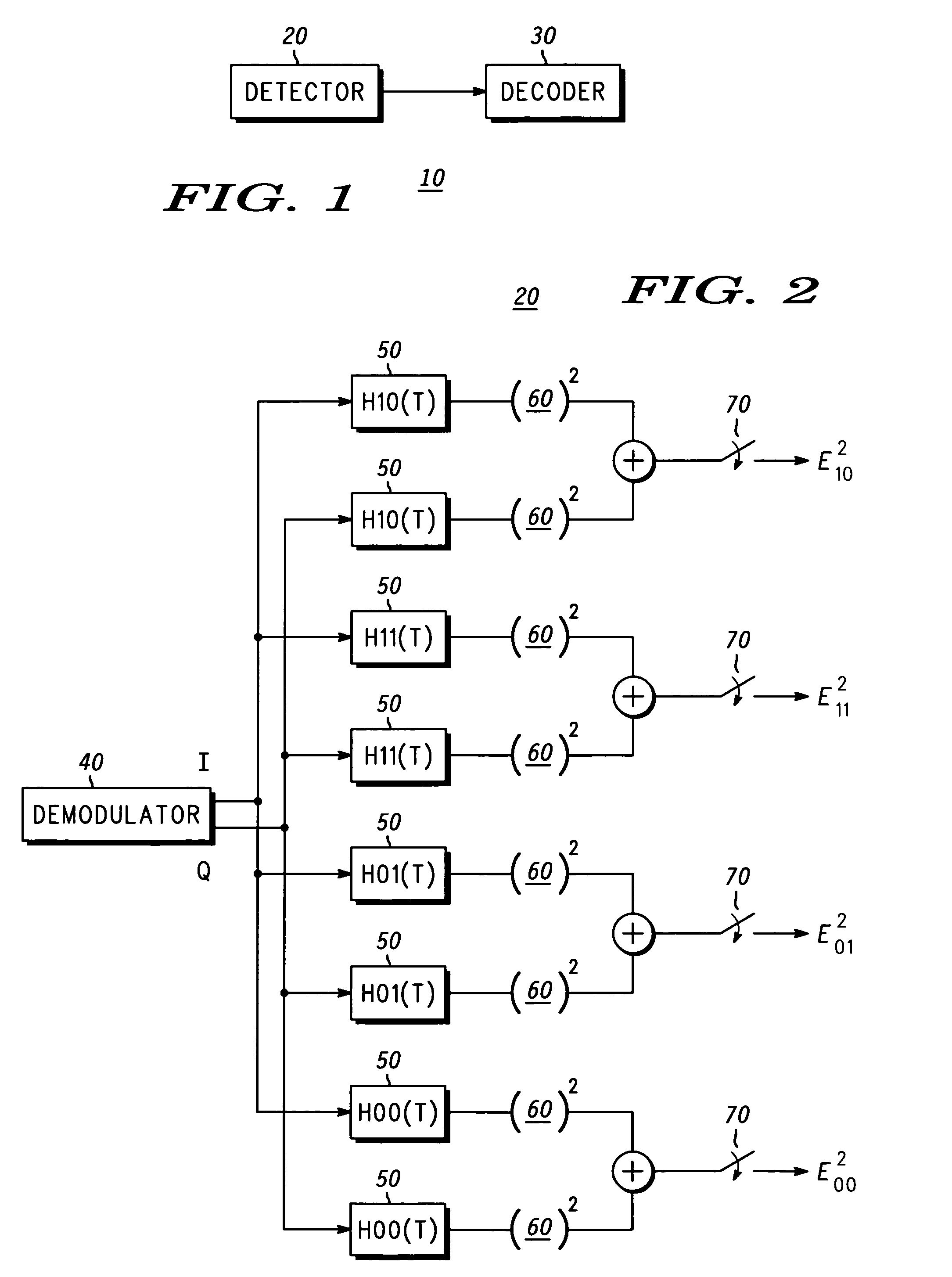
[0019]In the present invention, the detector 20 is an envelope detector as shown in greater detail in FIG. 2. Envelope detection is typically optimum for orthogonal frequency shift keying (FSK) signals, and although the signaling used in accordance with the FLEX protocol is not exactly orthogonal FSK, the performance is similar due to the baseband pulse shaping of the PAM signal. The construct and operation of an envelope detector are well known to those of ordinary skill in the art. Hence, for clarity and to prevent unnecessarily obscuring the instant invention, only a high-level discussion is provided.
[0020]As shown in FIG. 2, the detector 20 includes a demodulator 40 adapted to generate inphase (I) and quadrature (Q) signal components that are provided to a bank of filters 50. In the illustrated embodiment, the filters are matched to the FSK signal without Bessel filtering to provide an efficiency gain without significant performance degradation. The magnitudes of the inphase and...
second embodiment
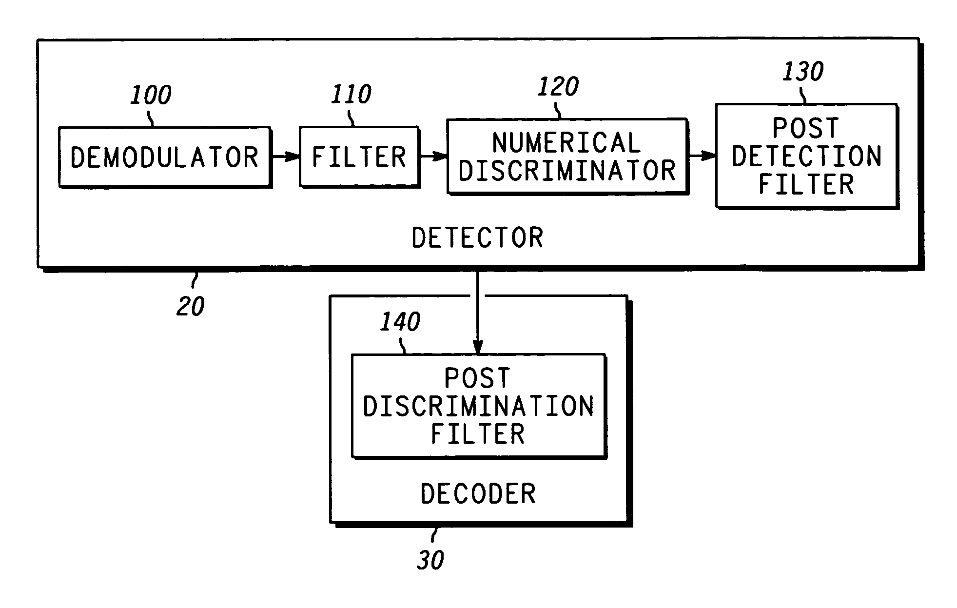
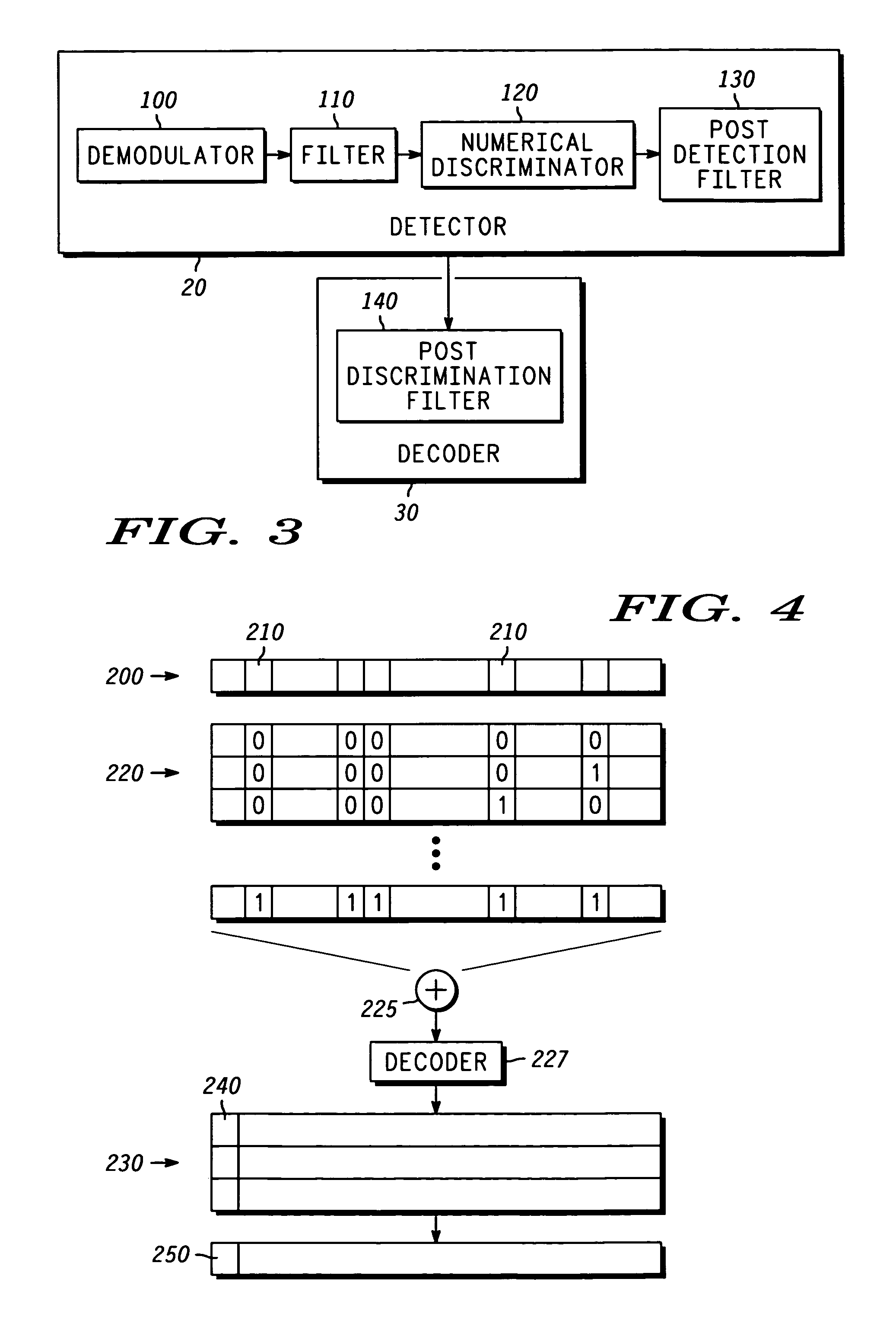
[0027]In the present invention, the detector 20 is a discriminator detector as shown in greater detail in FIG. 3. Discrimination detection may be implemented using commercially available analog FM demodulators. The construct and operation of a discriminator detector are well known to those of ordinary skill in the art. Hence, for clarity and to prevent unnecessarily obscuring the instant invention, only a high-level discussion is provided.
[0028]The detector 20 includes a demodulator 100, a filter 110, a numerical discriminator 120, and a post detection filter 130. In the illustrated embodiment, the filter 110 includes a first stage 2nd order Butterworth filter with a 3 dB bandwidth of 11 kHz and a second stage 6th order Butterworth filter with a 3 dB bandwidth of 16 kHz. The numerical discriminator 120 produces a baseband signal that is similar to the filtered PAM signal generated at the transmitter (not shown), however, the baseband signal is passed through the post detection filte...
PUM
 Abstract
Description
Claims
Application Information
PatSnap Eureka turns technology decisions into work you can execute. Powered by our Innovation Knowledge Graph, it runs expert workflows across engineering, life sciences, materials and intellectual property. Get your review-ready output in minutes.


