Image processing system, image processing method, and image processing program

a technology of image processing and image processing method, applied in the field of image processing system, image processing method, image processing program, can solve the problems of degrading image quality, noise appearing in regions where there is a large difference in luminance, and the boundary of these blocks is perceived by a user as noise, so as to reduce the influence of an error in determination, reduce the influence of mosquito noise, and facilitate the process

Active Publication Date: 2006-05-30
GK BRIDGE 1
View PDF8 Cites 112 Cited by
  • Summary
  • Abstract
  • Description
  • Claims
  • Application Information

AI Technical Summary

Benefits of technology

[0083]Mosquito noise is notable in a region adjacent to a strong edge. Therefore, mosquito noise can be reduced by changing the evaluation values for turning on/off filtering according to the approximate size of an edge contained in a block. Edge extraction is performed only on neighboring pixels in order to use a process using neighborhood difference values. In addition, the maximum values of difference betwee

Problems solved by technology

When JPEG or MPEG technology is used, two types of noise, which will be described below, are generated, degrading image quality.
The boundaries of these blocks are perceived by a user as noise.
As a result, noise appears in regions where there is a large difference in luminance between a boundary and the surrounding region.
However, the technique described in Japanese Patent Laid-Open No. 3-46482 is insufficient for removing block distortion because it makes a correction to boundary pixels only.
The VM and the technique described in Japanese Paten

Method used


Image

  • Image processing system, image processing method, and image processing program
  • Image processing system, image processing method, and image processing program
  • Image processing system, image processing method, and image processing program

Examples


first embodiment

[0098]the present invention will be described first.

[0099]Like parts are labeled with like reference numerals in the drawings referenced in the following description.

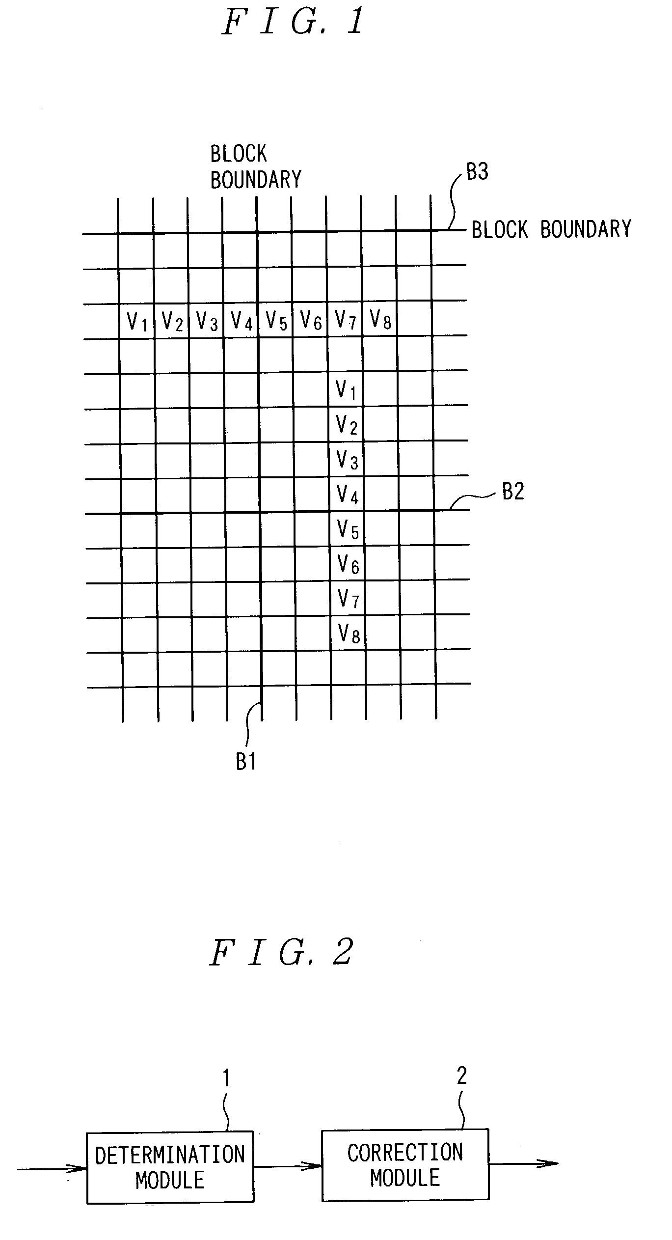
[0100]FIG. 2 shows a block diagram of the embodiment of the image processing system according to the present invention. As shown, the image processing system according to the present invention comprises a determination module 1 for referencing 2N pixels, including a pixel on the boundary, consist of N pixels on each side of a boundary and run orthogonally to that boundary, and determining whether correction should be performed; and a correction module 2 for using each set of M pixels on each side of the boundary to perform correction if the determination module 1 determines that correction should be performed, where N is an integer between 3 and 5 inclusive and M is an integer smaller than N.

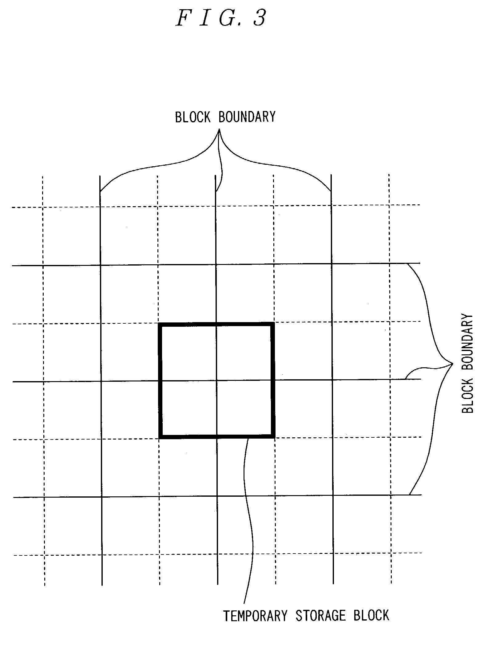
[0101]A buffer may be provided for temporarily holding a block to which filtering is to be applied. For example, if four pixels on...

second embodiment

[0136]the present invention will be described below with respect to the accompanying drawings, in which like reference characters refer to the same parts throughout the different views.

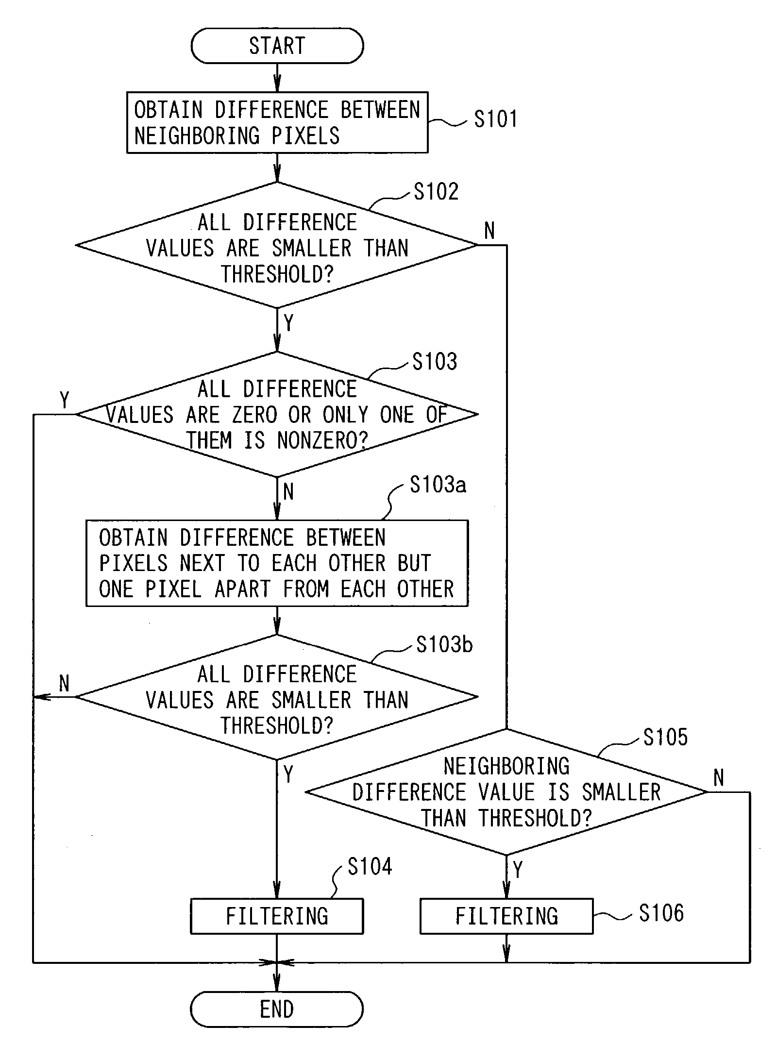
[0137]FIG. 7 shows a block diagram of one embodiment of an image processing system according to the present invention. As shown in FIG. 7, the image processing system according to this embodiment comprises a maximum value finding module 3 for obtaining the maximum value of difference values between neighboring pixels, including a boundary pixel, in at least half of all the pixels composing a block to be processed; a difference value calculation module 4 for calculating difference values between 2N pixels, including the boundary pixel, that consist of N pixels on each side of the boundary and run orthogonally to the boundary; a determination module for comparing the difference values calculated by the difference value calculation module 4 with a threshold corresponding to the maximum value to determine...


PUM


Abstract

In the present invention, 2N pixels (having signal levels V1 through V8), including a boundary pixel, that consist of N pixels on each side of a boundary and run orthogonally to the boundary are referenced to determine whether correction should be performed or not. If it is determined that the correction should be performed, the boundary pixel and M pixels on each side of the boundary pixel are used to perform the correction. In an image processing system for performing filtering on pixels belonging to a block, which is a unit of discrete cosine transform in image compression, the maximum value of differences between neighboring pixels in at least half, including a pixel of interest, of all the pixels composing a block to be processed is obtained. Differences between neighboring pixels in 2N pixels, including the pixel of interest, that run orthogonally to the boundary between blocks and consist of N pixels on each side of the boundary are calculated. The differences calculated are compared with a threshold corresponding to the maximum value to determine whether filtering should be performed. If it is determined that filtering should be performed, the pixel of interest and M pixels on each side of the pixel of interest are used to perform filtering. N is a positive integer and M is a positive integer smaller than N.

Description

TECHNICAL FIELD[0001]The present invention relates to an image processing system, image processing method, and image processing program.BACKGROUND ART[0002]JPEG (Joint Photographic Experts Group) compression, which is as till image compression technology, and MPEG (Moving Picture Experts Group) compression, which is a motion picture compression technology, are widely known. These image compression technologies treat an 8×8-pixel block as a processing unit to perform the well-known Discrete Cosine Transform (hereinafter referred to as DCT). The DCT is a process for separating an image into spatial frequency components that can reduce spatially redundant information to compress that image.[0003]When JPEG or MPEG technology is used, two types of noise, which will be described below, are generated, degrading image quality. In the JPEG and MPEG technologies, an 8×8-pixel block is treated as a processing unit. The boundaries of these blocks are perceived by a user as noise. The boundary n...

Claims


Application Information

Patent Timeline
IPC IPC(8): G06K9/40G06K9/00H04N7/26H04N7/30
CPCH04N19/86H04N19/527
Inventor ISHIKAWA, MASAKI
Owner GK BRIDGE 1
Why Eureka
Try Eureka