IC card
- Summary
- Abstract
- Description
- Claims
- Application Information
AI Technical Summary
Benefits of technology
Problems solved by technology
Method used
Image

Examples
embodiment 1
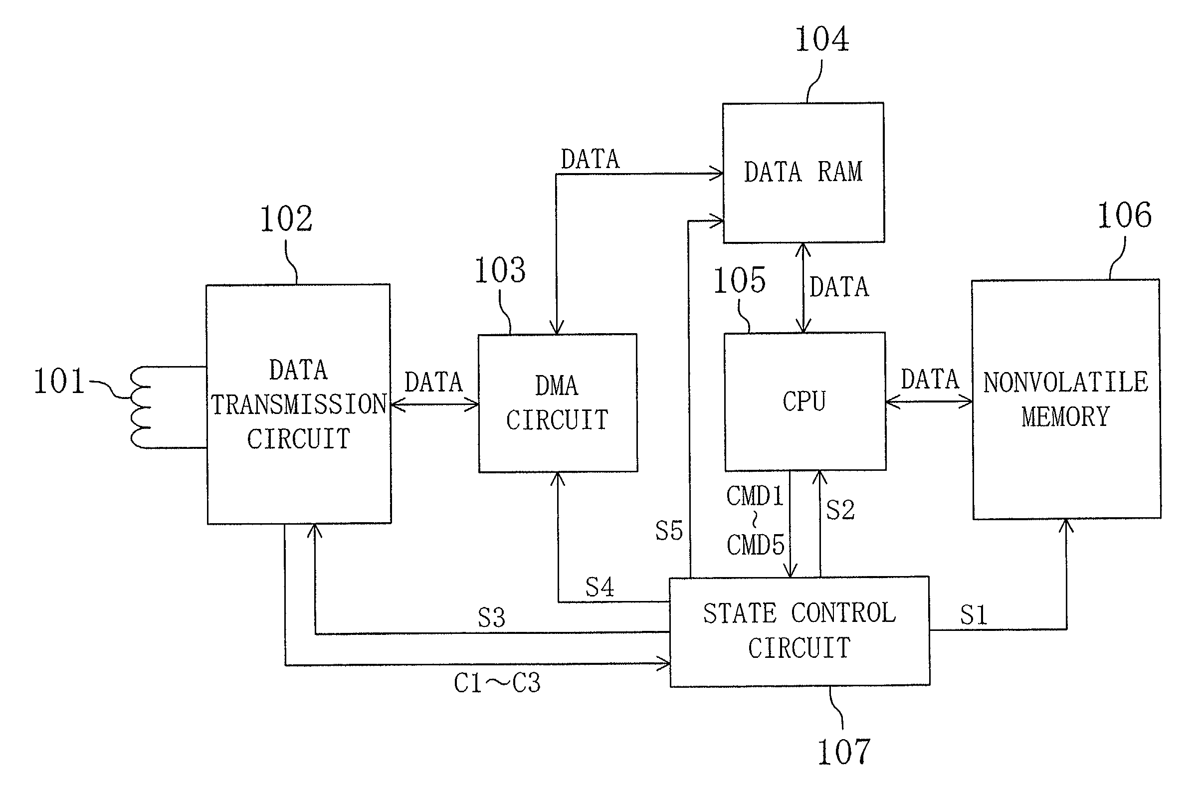
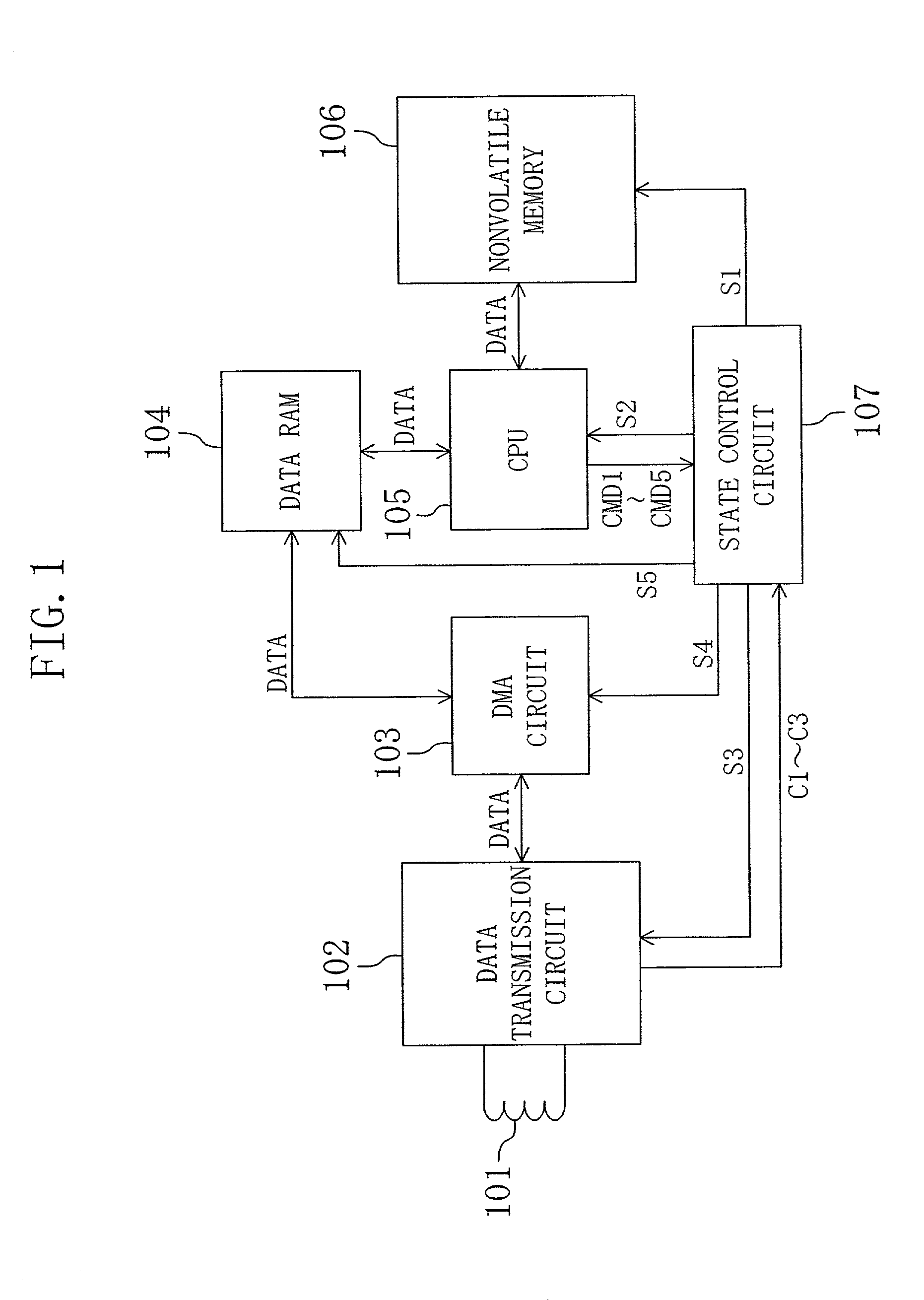
[0044]FIG. 1 is a block diagram for showing the configuration of an IC card according to Embodiment 1 of the invention. Referring to FIG. 1, the IC card includes an antenna 101, a data transmission circuit 102, a DMA circuit 103, a data RAM 104, a CPU 105, a nonvolatile memory 106 and a state control circuit 107.
[0045]The antenna 101 receives a signal sent from a reader / writer (not shown) and sends a signal to the reader / writer. This sending / receiving is carried out in a contactless manner by using electric waves as a medium. Also, the antenna 101 receives power from the reader / writer by using electromagnetic waves as a medium. This power serves as the operation power of the IC card.
[0046]The data transmission circuit 102 processes a signal received by the antenna 101 and transmits the processed signal to the DMA circuit 103. Also, the data transmission circuit 102 processes a signal transmitted from the DMA circuit 103 and transmits the processed signal to the antenna 101. Furtherm...
embodiment 2
[0085]An IC card according to Embodiment 2 of the invention includes a data transmission circuit 400 shown in FIG. 4 instead of the data transmission circuit 102 of FIG. 1. Referring to FIG. 4, the data transmission circuit 400 includes, in addition to the function of the data transmission circuit 102 of FIG. 1, a send / receive processing circuit 401 and a data transfer timing generation circuit 402.
[0086]The send / receive processing circuit 401 determines the state of a receive signal and a send signal from and to an analog circuit part (not shown) included in the data transmission circuit 400 in accordance with the standard of ISO / IEC 14443-3, and outputs state information SMT corresponding to the state.
[0087]The data transfer timing generation circuit 402 outputs an interruption signal C3 to the state control circuit 107 in response to state information SMT corresponding to “a signal currently received by the data transmission circuit 400 being in a period of a stop bit”, state inf...
embodiment 3
[0106]In the data transmission circuit 102 of FIG. 1, a signal received by the antenna 101 is modulated into digital data by an analog circuit part (not shown) such as a modulator, so as to obtain a receive signal as shown in FIG. 7. As shown in FIG. 7, a receive signal is composed of an SOF, a data portion and an EOF and is at a logical high level when the data transmission circuit 102 is in a state other than the receive state. Also, the SOF has a structure according with the standard of ISO / IEC 14443-3 as shown in FIG. 5. The SOF is composed of a fall at a first logical level, 10-etu period low (logical low level) at a second logical level, a rise within 1 etu at a third logical level and 2 through 3-etu period high (logical high level) at a fourth logical level. It is noted that etu is a unit of time.
[0107]However, when the data transmission circuit 102 is in a state other than the receive state, the analog circuit part can be affected by noise caused by the operations of the CP...
PUM
 Abstract
Description
Claims
Application Information
 - R&D
- Intellectual Property
- Life Sciences
- Materials
- Tech Scout
- Unparalleled Data Quality
- Higher Quality Content
- 60% Fewer Hallucinations
Browse by: Latest US Patents, China's latest patents, Technical Efficacy Thesaurus, Application Domain, Technology Topic, Popular Technical Reports.
© 2025 PatSnap. All rights reserved.Legal|Privacy policy|Modern Slavery Act Transparency Statement|Sitemap|About US| Contact US: help@patsnap.com