Freight container and lift casting therefore and method for lifting and transporting same

a technology for lifting casting and freight containers, applied in the field of large freight containers, can solve the problems of reducing the available storage volume of containers, difficult loading containers, and high cost of both cargo and cargo, and achieve the effects of reducing bending stresses, reducing fatigue stresses, and reducing bending stresses in freight containers

Inactive Publication Date: 2006-06-06
BNSF RAILWAY
View PDF12 Cites 26 Cited by
  • Summary
  • Abstract
  • Description
  • Claims
  • Application Information

AI Technical Summary

Benefits of technology

[0018]It is another objective of the present invention to provide an improved lift casting for use on freight containers, the improved lift casting being of shorter height, thereby creating less intrusion into the interior of the container.
[0024]It is another objective of the present invention to provide a method of preventing fatigue failure in freight containers.

Problems solved by technology

Unfortunately, due to height restrictions and strength requirements, lift castings and stack castings must protrude into the interior of the container.
This intrusion not only reduces the available storage volume of the container, but makes it difficult to load the container, as well.
This is costly both in the amount of cargo that can be shipped, and in the additional time required to load a container.
Although larger containers are able to hold a greater volume of freight, significant structural problems arise when larger containers are used in conjunction with smaller containers in the overall intermodal transportation system.
This offset creates undesirable bending moments and bending stresses in the reinforcement beams and castings of both containers, thereby causing the reinforcement beams and castings on the containers to buckle and fail under the bending loads.
In addition, because prolonged vibration of stacked containers in intermodal transportation often leads to fatigue failure of the reinforcement beams, constant and expensive container maintenance and inspection programs are required.
Some containers have lift castings that do not allow other containers to be stacked on top of the container at all.
However, due to the long life of these freight containers, and the large number of older containers currently in service, it is inevitable that new containers will be used in intermodal transportation systems with existing containers.

Method used


Image

  • Freight container and lift casting therefore and method for lifting and transporting same
  • Freight container and lift casting therefore and method for lifting and transporting same
  • Freight container and lift casting therefore and method for lifting and transporting same

Examples


Embodiment Construction

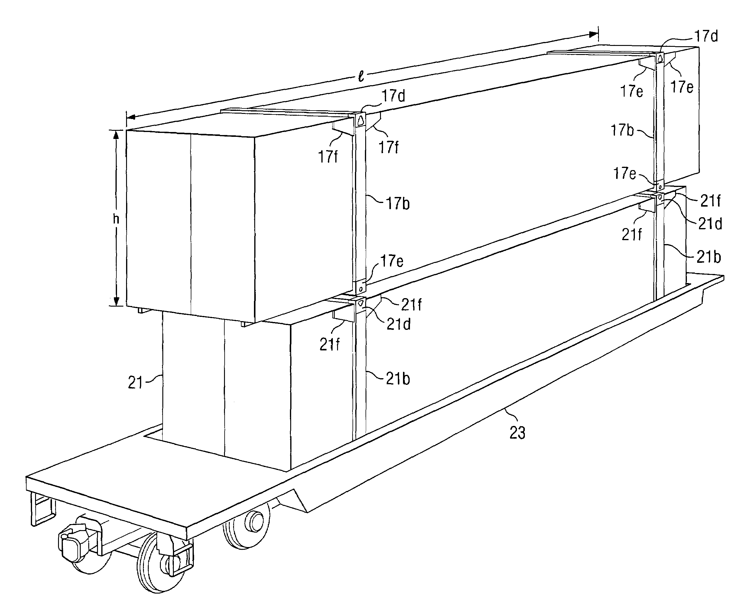
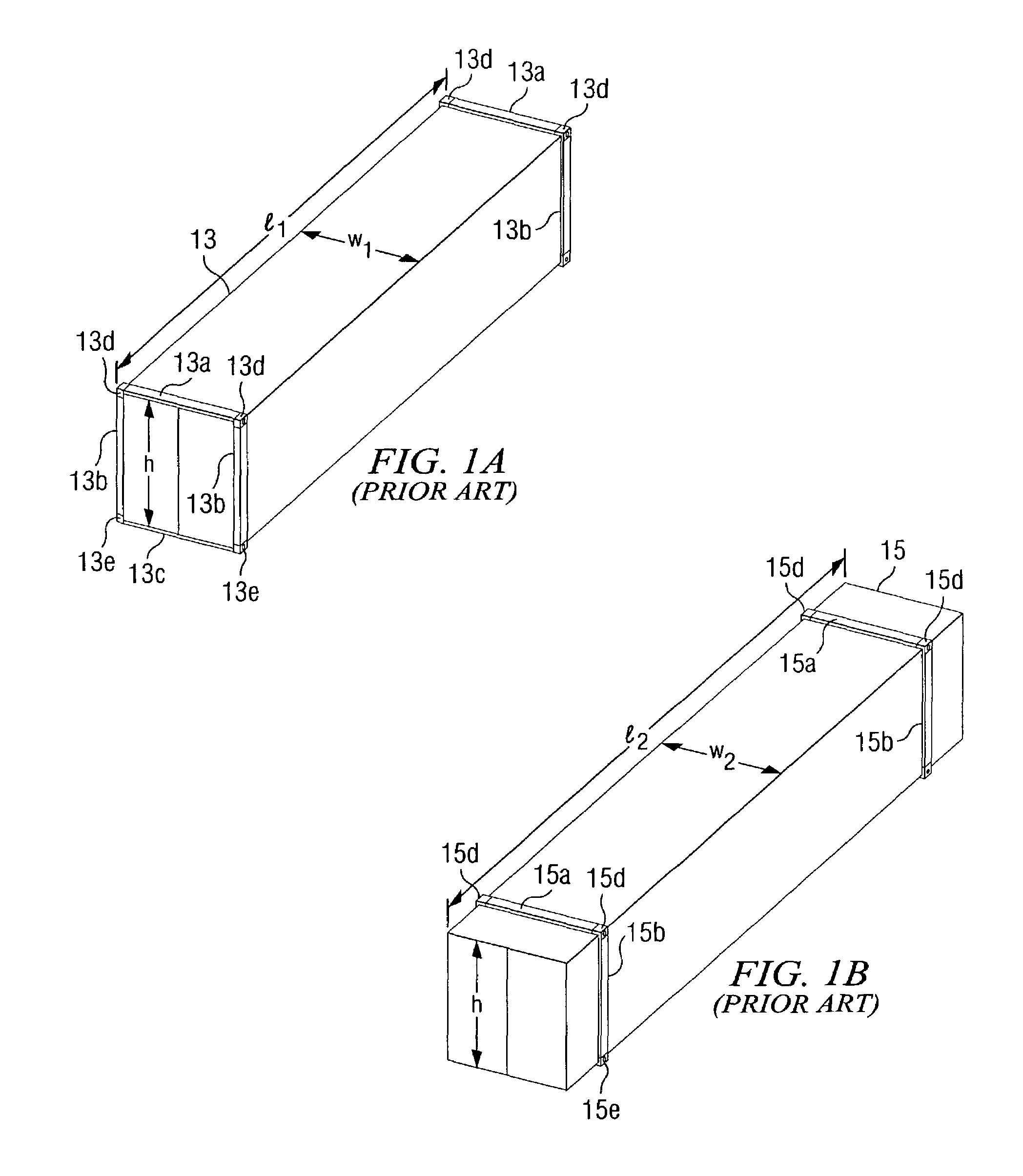
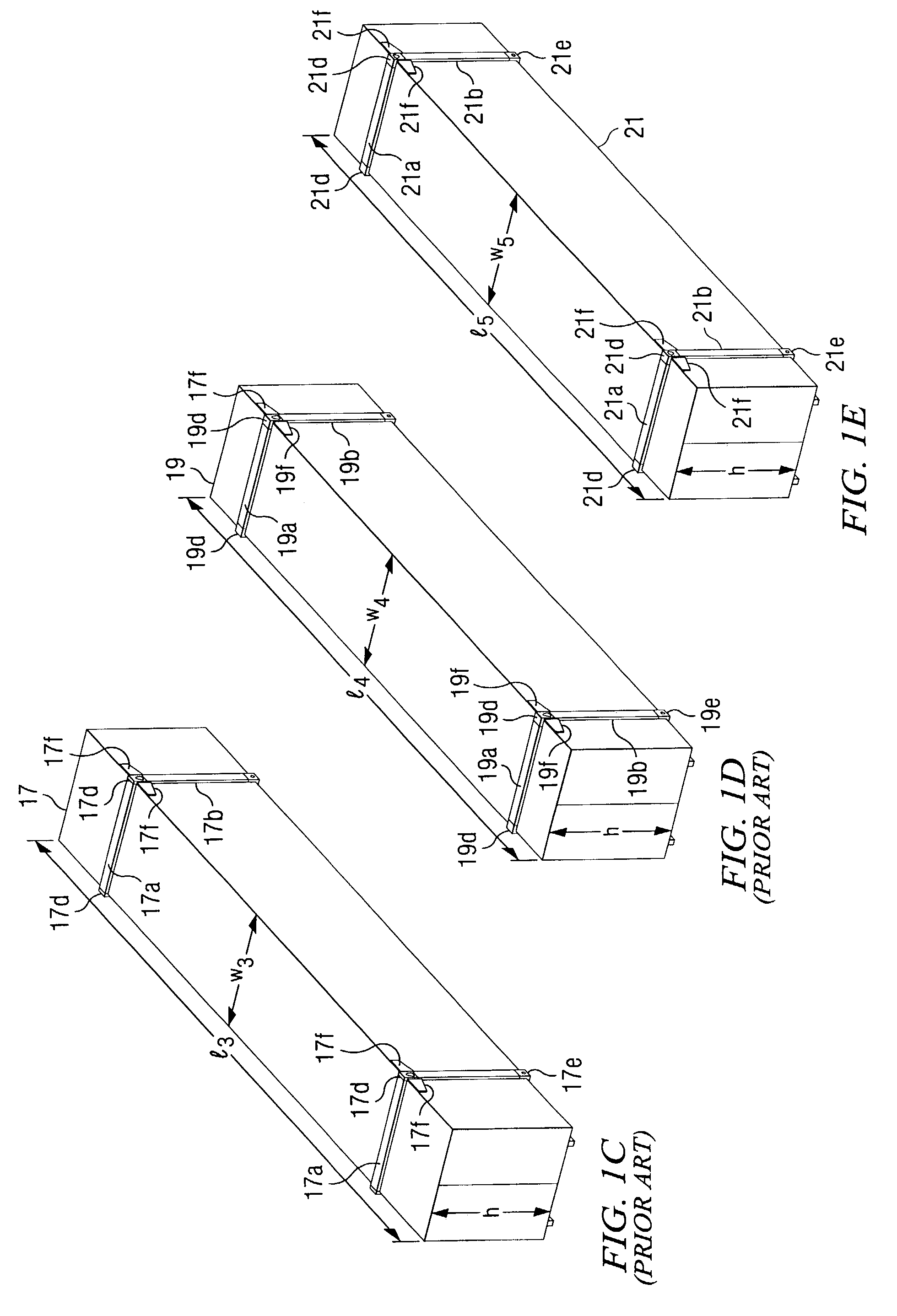
[0039]Referring to FIGS. 1A–1E in the drawings, a plurality of prior-art intermodal freight containers 11, 13, 15, 17, and 19 are illustrated. Intermodal freight container 21 is illustrative of the preferred embodiment of the present invention. Containers 13, 15, 17, 19, and 21 represent an evolution in intermodal freight container technology. Although containers 13, 15, 17, 19, and 21 are generally all of the same height h, containers 13, 15, 17, 19, and 21 may be classified by their differing lengths and widths. For example, container 13 represents a conventional ISO container having a length l1 of 40′ and a width w1 of 96″; container 15 represents a conventional “domestic” container having a length l2 of 48′ and a width w2 of 102″; container 17 represents a conventional container, typical of containers used by the J.B. Hunt Company, having a length l3 of 53′ and a width w3 of 102″; and container 19 represents another typical J.B. Hunt container having a length l4 of 48′ and a wid...


PUM


Abstract

An improved freight container for use in intermodal freight transportation systems that includes lift castings having a top lift aperture located on the lift casting at an outboard position, such that when other containers are stacked on top of the improved container, loads are properly distributed through reinforcement beams of the improved container, thereby substantially reducing bending stresses in the improved container, substantially reducing the possibility fatigue failure of the improved container, and reducing the costs of maintenance and inspection of the improved container.

Description

[0001]This application is a Divisional application of U.S. patent application Ser. No. 09 / 274,919 filed on 23 Mar. 1999, now U.S. Pat. No. 6,572,325 for FREIGHT CONTAINER AND LIFT CASTING THEREFORE AND METHOD OF LIFTING AND TRANSPORTING SAME.BACKGROUND ART[0002]1. Field of the Invention[0003]The present invention relates generally large freight containers used in intermodal freight transportation systems, in which the freight containers are stacked upon each other and transported by truck, rail, ship, and combinations thereof. In particular, the present invention relates to a freight container having an improved lift casting that are compatible with existing lift mechanisms and existing freight containers.[0004]2. Description of Related Art[0005]Large freight containers used in intermodal freight transportation systems are well known in the art. The intermodal freight transportation industry has always been very competitive. As with most competitive industries, any technological inn...

Claims


Application Information

Patent Timeline
Patent Type & Authority Patents(United States)
IPC IPC(8): B66C1/66B65D88/02B65D88/12B65D90/00
CPCB65D88/022B65D88/121B65D90/0026B66C1/663B65D90/0013Y10T403/77
Inventor KELLY, THOMAS P.
Owner BNSF RAILWAY
Why Eureka
Try Eureka