
Pump

a technology of displacement pump and pump body, which is applied in the direction of positive displacement pump, pump, liquid fuel engine, etc., can solve the problems of loss of pressure, fatigue damage, deterioration reliability, etc., and achieves the effect of less displacement, increased suction flow rate, and high efficiency

Active Publication Date: 2006-06-06
SEIKO EPSON CORP
View PDF17 Cites 11 Cited by
  • Summary
  • Abstract
  • Description
  • Claims
  • Application Information

AI Technical Summary

Benefits of technology

[0011]Accordingly, the present invention provides a pump with high driving efficiency in which the number of mechanical switching valves is decreased to reduce pressure loss and reliability is enhanced, and which is ready for high load pressure and high-frequency driving, and which increases the discharged fluid volume of the pump.
[0017]Providing the cycle control device prevents or reduces useless consumption of the removed fluid volume to increase the volume and pressure of the discharged fluid of the pump, thus providing a pump with high driving efficiency.
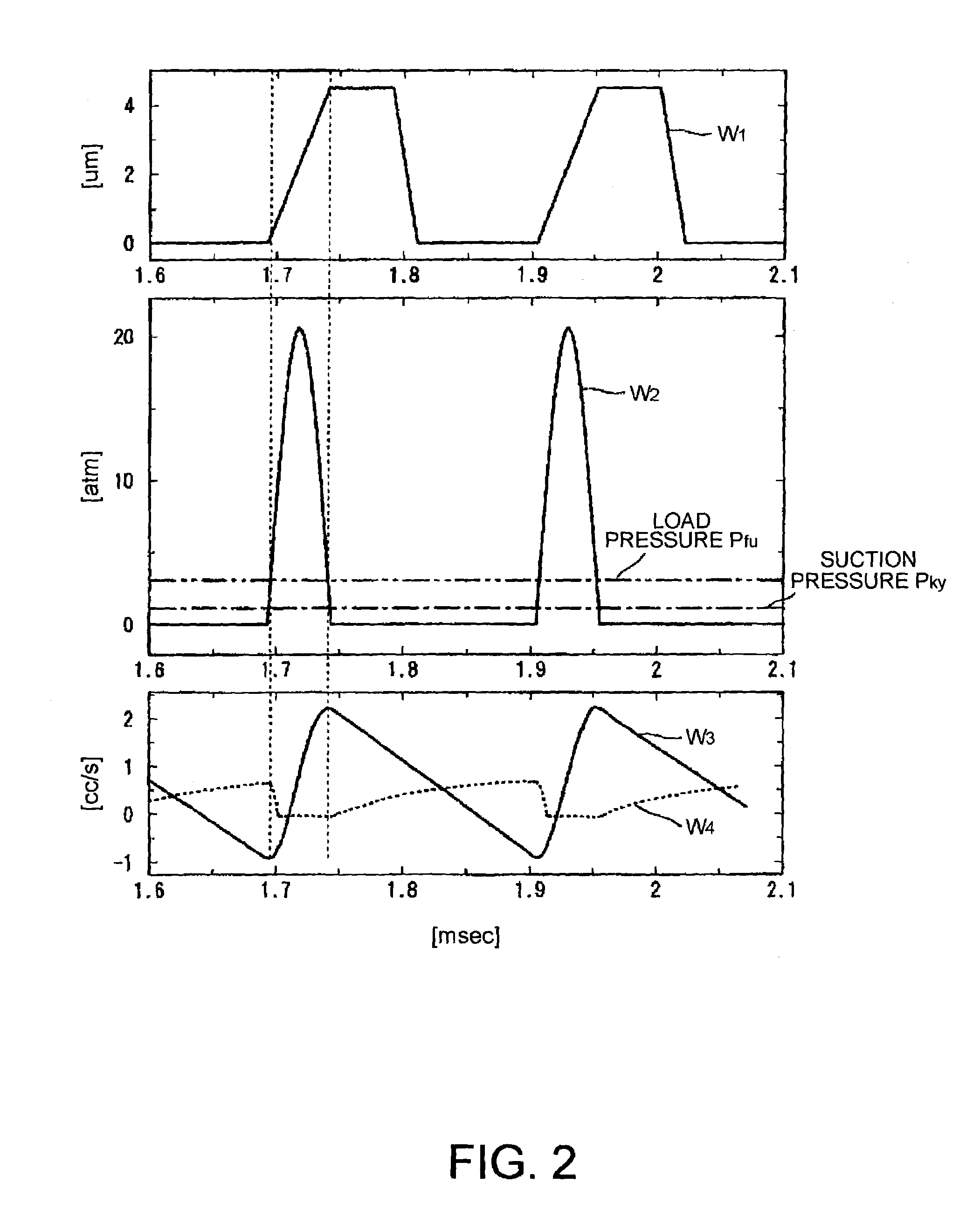
[0037]According to the invention, discharged fluid volume can be increased and the durability of the check valve can be enhanced.
[0040]The actuator itself can be driven with less displacement without decreasing the volume of fluid discharged from the pump, so that the inner loss of the actuator is decreased, thus offering an advantage of driving the pump with high efficiency.

Problems solved by technology

The arrangement of JP 357, however, poses a problem that both the suction channel and the discharge channel require a check valve, causing a loss of pressure when fluid passes through the two check valves.
Also, the check valves are repeatedly opened and closed, causing possible fatigue damages.
There is also a problem of deteriorating reliability with an increase in the number of the check valves.
With the arrangement of JP 537, however, activation is allowed only with low frequency, as described above, thus posing a problem in that a compact high-output pump cannot be provided.
Accordingly, backflow is increased with an increase in the external pressure (load pressure) at the pump outlet, thus posing a problem that the pump does not operate at high load pressure.

Method used


Image

  • Pump
  • Pump
  • Pump

Examples


Embodiment Construction

[0063]Exemplary embodiments of the present invention are described with reference to the drawings below.

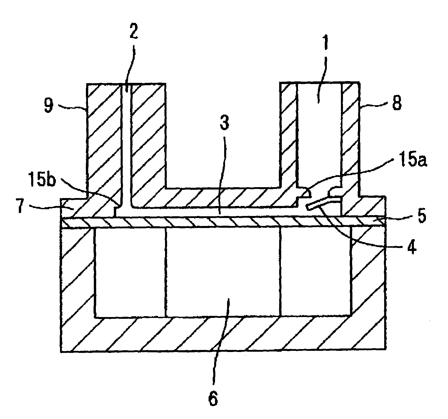
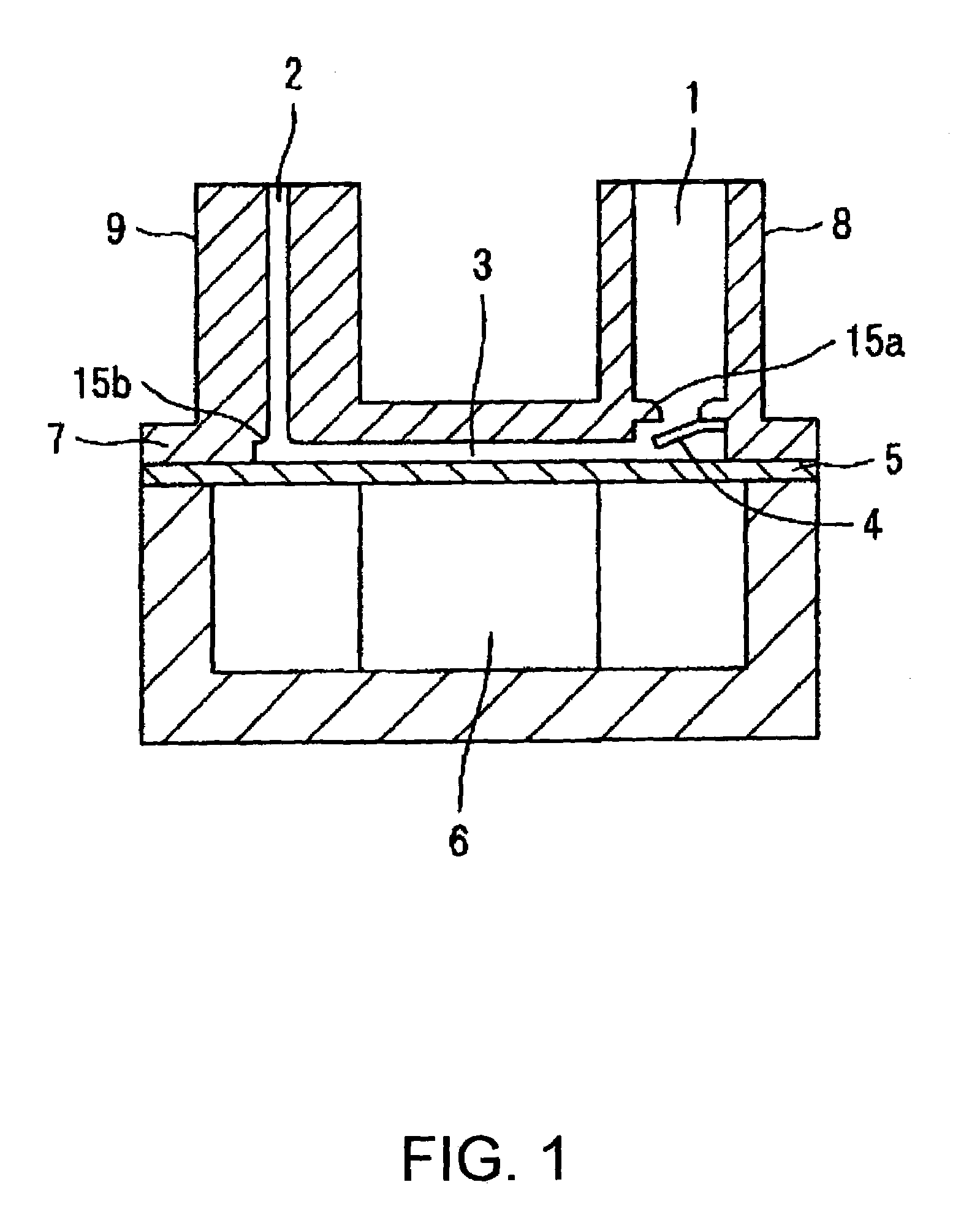
[0064]Referring to FIG. 1, the arrangement of a pump according to the exemplary embodiments of the present invention are described below. FIG. 1 is a longitudinal sectional view of the pump of the present invention, in which a circular diaphragm 5 is arranged on the bottom of a cylindrical casing 7. The outer edge of diaphragm 5 is fixed to the casing 7 such that it can be elastically deformed. A piezoelectric element 6 extending vertically in the drawing is arranged on the bottom of the diaphragm 5, as an actuator to move the diaphragm 5.

[0065]A narrow space between the diaphragm 5 and the top wall of the casing 7 serves as a pump chamber 3. A suction channel 1 and a discharge channel 2 are opened to the pump chamber 3, the suction channel 1 having a check valve 4 serving as a fluid resistive element and the discharge channel 2 being a tubular channel including a narrow hole whic...


PUM


Abstract

The invention provides a pump with high driving efficiency in which the number of mechanical switching valves is decreased to reduce pressure loss and increase reliability, and which is ready for high load pressure and high-frequency driving, and which increases the discharged fluid volume for one cycle of pumping. A circular diaphragm arranged on the bottom of a casing has the outer edge fixed to the casing. The diaphragm includes a piezoelectric element to move the diaphragm on the bottom surface thereof. The space between the diaphragm and the top wall of the casing serves as a pump chamber, wherein a suction channel and a discharge channel are opened to the pump chamber, the suction channel having a check valve serving as a fluid resistive element and the discharge channel being always communicated with the pump chamber, even during the operation of the pump. In the pump, the activation of the piezoelectric element is controlled by a cycle control device so as to provide the cycle of the diaphragm in which the volume and the pressure of the discharged fluid of the pump are increased.

Description

BACKGROUND OF THE INVENTION[0001]1. Field of Invention[0002]The present invention relates to a positive displacement pump in which the capacity in a pump chamber is changed with a piston, a diaphragm or other device to move fluid. More specifically, the invention relates to a reliable pump with high flow rate.[0003]2. Description of Related Art[0004]Such related art pumps have an arrangement in which check valves are disposed between a suction channel and a discharge channel. A pump chamber is provided that has a capacity that can be varied. Such a pump is disclosed in Japanese Unexamined Patent Application Publication No. 10-220357 (JP 357).[0005]The related art also includes an arrangement of a pump to produce one-directional flow using viscous resistance of fluid, which has a valve in the discharge channel. When the valve is opened, the suction channel has higher fluid resistance than the discharge channel. Such a pump is disclosed in Japanese Unexamined Patent Application Public...

Claims


Application Information

Patent Timeline
IPC IPC(8): F04B17/03F04B49/00F04B9/00F04B43/04F04B49/06
CPCF04B49/065F04B43/046
Inventor TAKAGI, KUNIHIKOSETO, TAKESHI
Owner SEIKO EPSON CORP
Learn More