
Discharge valve apparatus for reciprocating compressor

a reciprocating compressor and discharge valve technology, applied in the direction of machines/engines, liquid fuel engines, positive displacement liquid engines, etc., can solve the problems of noise generation, noise generation, and inability to move the discharge valve b>5/b> stable, and achieve the effect of reducing noise and abrasion

Inactive Publication Date: 2006-06-06
LG ELECTRONICS INC
View PDF44 Cites 3 Cited by
  • Summary
  • Abstract
  • Description
  • Claims
  • Application Information

AI Technical Summary

Benefits of technology

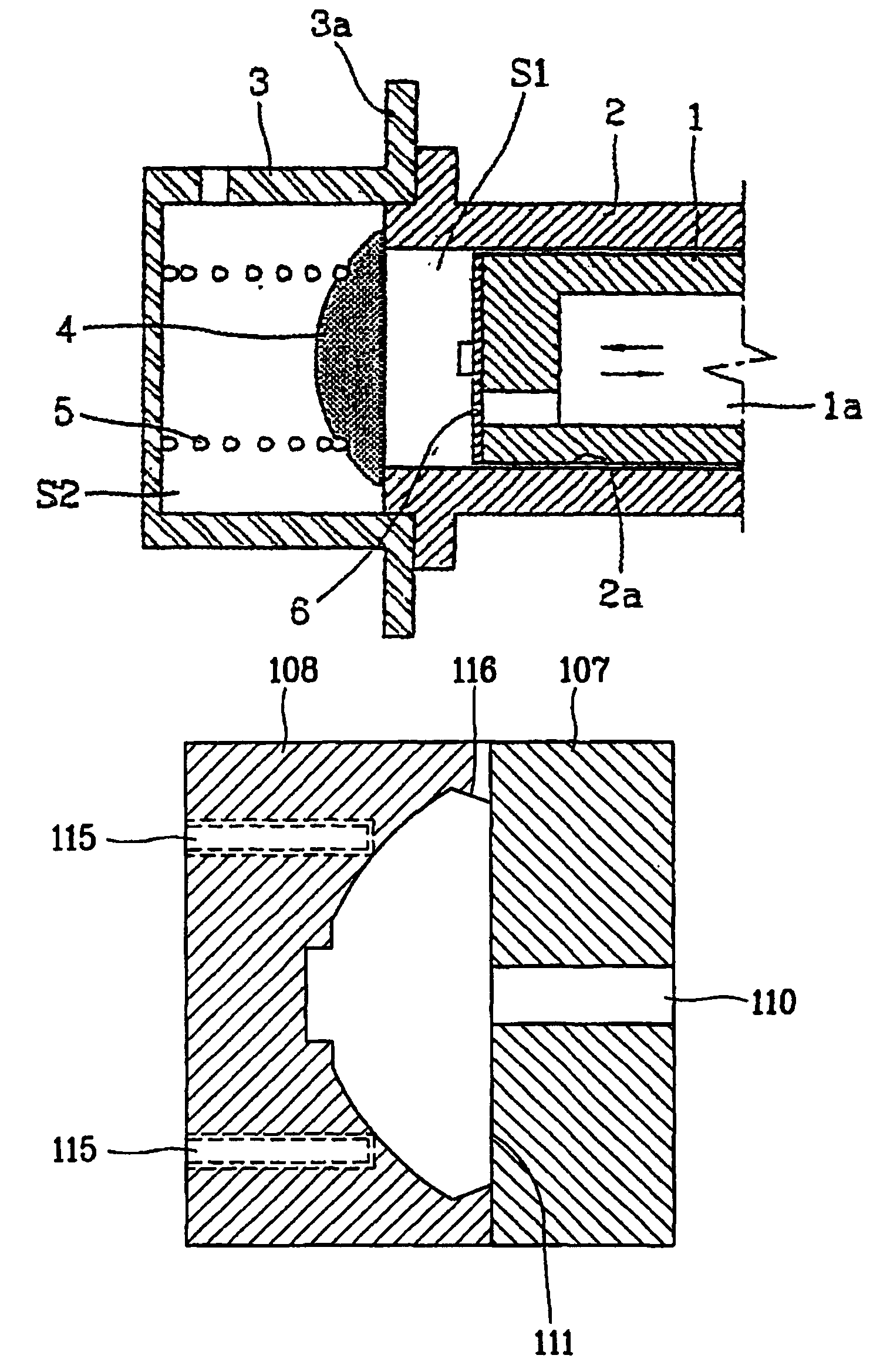
[0022]Therefore, an object of the present invention is to provide a discharge valve apparatus for a reciprocating compressor which can block impact noise by preventing respective parts of a valve spring from impacting with each other even if the valve spring is compressed during compression and discharge strokes of a piston.
[0024]Also, still another object of the present invention is to provide a discharge valve apparatus for a reciprocating compressor which can easily eject the discharge valve molding by forming a gate passage which is formed on the metal mold when the discharge valve is molded, on a first metal mold which is fixed.

Problems solved by technology

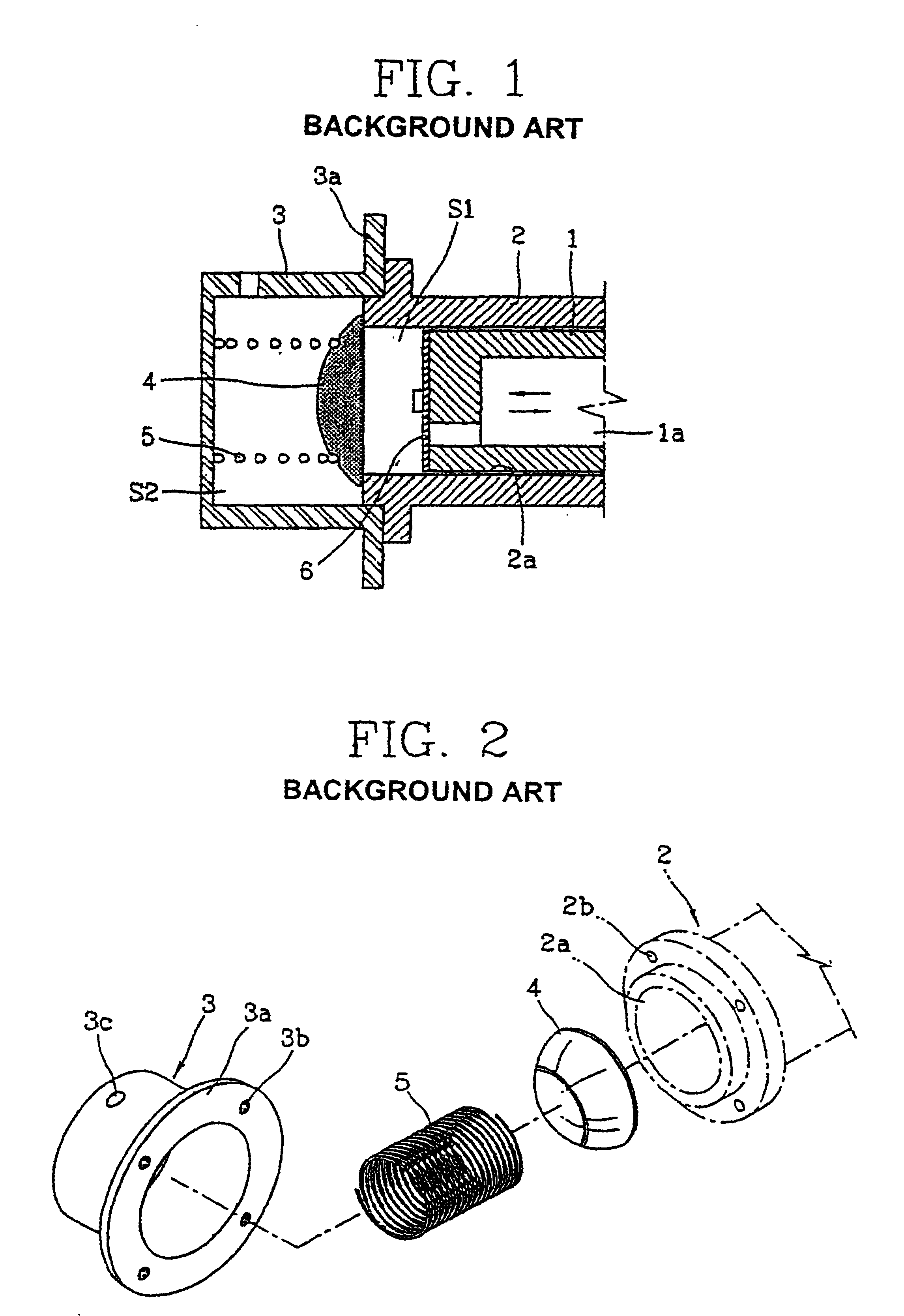
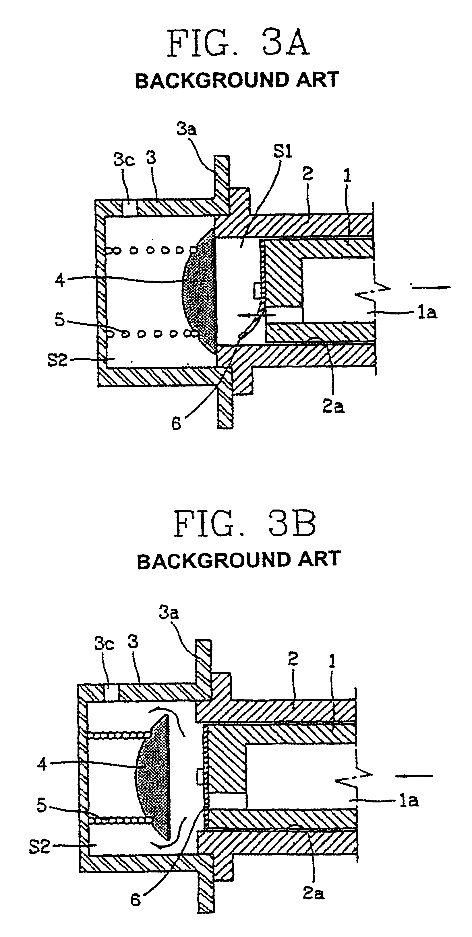
However, there are some problems as follows in the conventional discharge valve device.
In addition, the discharge valve is touches with inner wall surface of the discharge cover when the compression stroke is made, and therefore a noise and abrasion are generated.
Therefore, a noise is generated or the movement of the discharge valve 5 is not stable.
Also, in case that the gate of metal mold is formed on side surface of the discharge valve 5, the molded product may be distorted because of flowing characteristics of the injected medium and the movement of the discharge valve is not stable because of inequality in the medium density after molding, whereby the discharge noise is made.
In addition, in case that the gate is formed on the pressure face unit 14 direction, there is no machining allowance for post-fabrication, and therefore it is difficult to fabricate.

Method used


Image

  • Discharge valve apparatus for reciprocating compressor
  • Discharge valve apparatus for reciprocating compressor
  • Discharge valve apparatus for reciprocating compressor

Examples


Embodiment Construction

[0022]Therefore, an object of the present invention is to provide a discharge valve apparatus for a reciprocating compressor which can block impact noise by preventing respective parts of a valve spring from impacting with each other even if the valve spring is compressed during compression and discharge strokes of a piston.

[0023]Also, another object of the present invention is to provide a discharge valve apparatus for a reciprocating compressor in which a molded product stays adhering to a fixed metal mold by forming a parting line which is formed when the discharge valve is molded on center part of the molded product of the discharge valve.

[0024]Also, still another object of the present invention is to provide a discharge valve apparatus for a reciprocating compressor which can easily eject the discharge valve molding by forming a gate passage which is formed on the metal mold when the discharge valve is molded, on a first metal mold which is fixed.

[0025]In order to achieve the a...


PUM


Abstract

A discharge valve apparatus for a reciprocating compressor comprises a discharge cover having built-in volume so as to cover a front end surface of the cylinder; a discharge valve disposed so as to be contacted / separated to / from the front end surface of the cylinder by a piston which undergoes a reciprocating movement inside the cylinder; and a valve spring having both ends respectively adhered to rear side of the discharge valve and to inner surface of the discharge cover so as to elastically support the rear side of the discharge valve. A rotation radius of the valve spring of a conical type is formed to be gradually reduced or increased so that impacts of a part to other parts during the compression can be prevented. Accordingly, when the valve spring is compressed in accordance with the compression and discharge strokes of the piston, the impacting noise caused by the impacts of the respective parts in the valve spring can be prevented previously.

Description

[0001]This application is the national phase under 35 U.S.C. §371 of PCT International Application No. PCT / KR01 / 00827 which has an International filing date of May 19, 2001, which designated the United States of America and was published in English.TECHNICAL FIELD[0002]The present invention relates to a discharge valve apparatus for a reciprocating compressor, and particularly, to a shape of the valve spring of a valve assembly applied to a reciprocating compressor and to a fabrication method for the discharge valve.BACKGROUND ART[0003]Generally, an axial direction discharge valve assembly among valve assemblies of a general reciprocating compressor is a device in which a piston installed as a single body with an armature of a motor undergoes a linear reciprocating movement inside a cylinder, sucks a refrigerant gas, and compresses and discharges the refrigerant gas to moving direction of the opened / closed when the piston undergoes the reciprocating movement is closely related to a ...

Claims


Application Information

Patent Timeline
Patent Type & Authority Patents(United States)
IPC IPC(8): F04B39/00F04B39/10
CPCF04B39/102Y10T137/7936F04B17/00
Inventor LEE, HYUKPARK, JUNG-SIKSONG, GYE-YOUNGKU, BON-CHEOL
Owner LG ELECTRONICS INC
Learn More