Pulley unit

a technology of pulleys and pulleys, which is applied in the direction of mechanical equipment, hoisting equipment, gearing, etc., can solve the problems of reducing the prone to deterioration, and difficulty in ensuring the wide annular space capable of holding sufficient amount of lubricating oil, so as to enhance the ability of the pulley unit and enhance the lubricating

Inactive Publication Date: 2006-06-06
KOYO SEIKO CO LTD
View PDF19 Cites 18 Cited by
  • Summary
  • Abstract
  • Description
  • Claims
  • Application Information

AI Technical Summary

Benefits of technology

[0029]As described above, it is possible for the recess to hold and store more lubricating oil which moved toward the outer diameter side of the annular space by the rotation centrifugal force caused by the relative rotation between the pulley and the rotor. In addition, if the lubricating oil impregnating body is accommodated in the recess, it is possible to continuously and stably supply the lubricating oil to the storage space from the lubricating oil impregnating body even if lubricating oil is exhausted. With this feature, the lubricating effect can further be enhanced and thus, the ability of the pulley unit can be enhanced.

Problems solved by technology

Therefore, under present circumstances, it is difficult to secure wide annular space capable of holding sufficient amount of lubricating oil for lubricating raceways of inner and outer rings of the one-way clutch or the rolling bearing when the pulley unit is used in the alternator.
As a result, lubricating oil is not held and is prone to leak outside through the seal ring, and an amount of lubricating oil is decreased.
This results in that an amount of lubricating oil which is repeatedly used in the raceways of the inner and outer rings is increased, and the lubricating oil is prone to be deteriorated.

Method used


Image

  • Pulley unit
  • Pulley unit
  • Pulley unit

Examples


Embodiment Construction

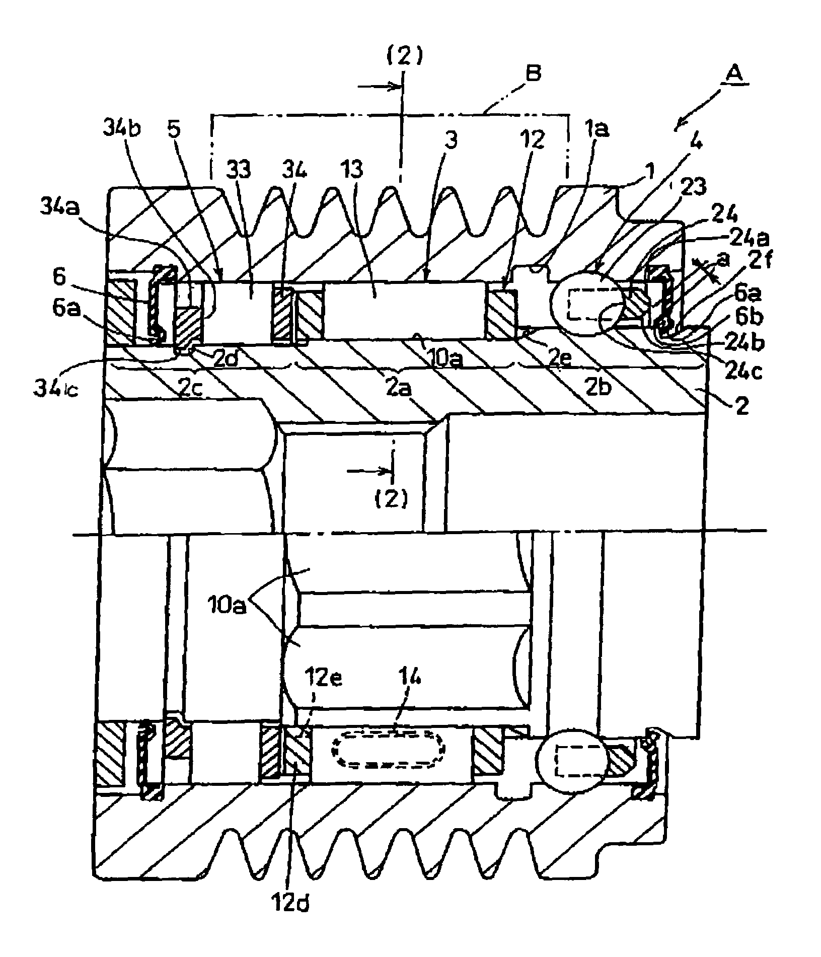
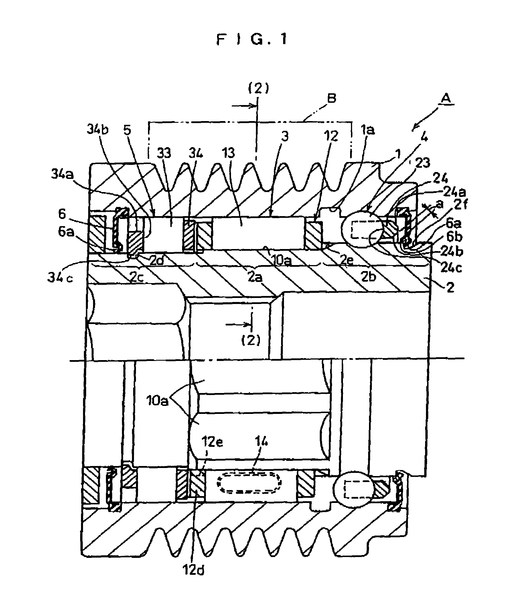
[0039]FIGS. 1 to 5 shows the best mode for carrying out the invention, wherein FIG. 1 is a vertical sectional view of a pulley unit according to a best mode for carrying out the present invention, FIG. 2 is a sectional view along a arrow of (2)—(2) in FIG. 1, FIG. 3 is a perspective view of a rotor shaft and a retainer of a one-way clutch in FIG. 1, FIG. 4 is a perspective view of a retainer of a ball bearing in FIG. 1 and FIG. 5 is a perspective view of a retainer of a roller bearing in FIG. 1.

[0040]In the illustrated example, a pulley unit A includes a pulley 1, a rotor shaft 2, a one-way clutch 3, a ball bearing 4 and a roller bearing 5 as rolling bearings, and a seal ring 6.

[0041]The hollow shaft 2 of the pulley unit A serves as an inner ring of each of the one-way clutch 3, the ball bearing 4 and the roller bearing 5. The pulley 1 of the pulley unit A serves as an outer ring of each of the one-way clutch 3, the ball bearing 4 and the roller bearing 5.

[0042]The pulley 1 is rotat...


PUM


Abstract

A pulley unit includes a pulley and a rotor concentrically disposed for relative rotation, a one-way clutch interposed in an annular space therebetween, rolling bearings provided on opposite sides of the one-way clutch, and a seal ring for sealing the annular space. An inner diametrical surface of the pulley forms an outer ring raceway of the one-way clutch and the rolling bearing, and an outer diametrical surface of the shaft body forms an inner ring raceway of the one-way clutch and the rolling bearing. An outer diameter side of an annular portion of a retainer of the rolling bearing on the side of the seal ring is reduced so as to increase a storage volume of lubricating oil between the rolling bearing and the seal ring.

Description

TECHNICAL FIELD[0001]The present invention relates to a pulley unit having a one-way clutch. The pulley unit can be mounted in an auxiliary machine which is driven by a crankshaft of an engine of an automobile or the like through a belt. Examples of the auxiliary machine are an air conditioner compressor, a water pump, an alternator, a cooling fan and the like of an automobile.BACKGROUND TECHNIQUE[0002]Various auxiliary machines mounted in automobile engines are driven by crankshafts of engines through belts. For example, when an alternator is connected to a crankshaft of the engine such that the alternator rotates in synchronization with the crankshaft, if the number of rotation of the crankshaft is lowered, electric power generation ability is lowered.[0003]Thereupon, there is proposed a pulley unit in which a one-way clutch is incorporated in the pulley of the alternator, and when the number of rotation of the crankshaft is lowered, the rotation of a rotor of the alternator is co...

Claims


Application Information

Patent Timeline
Patent Type & Authority Patents(United States)
IPC IPC(8): F16H55/36F16H7/20F16C19/49F16C33/32F16C33/34F16C33/41F16C33/46F16C33/66F16D41/06F16D41/067F16H55/49
CPCF16D41/067F16H55/49F16H55/36F16H2055/366F16C2361/63F16C19/49F16D2041/0608
Inventor FUJIWARA, HIDEKIICHIHARA, TAKAHIROTERADA, TADAHIROUEDA, MICHIRU
Owner KOYO SEIKO CO LTD
Why Eureka
Try Eureka