Finishing machine using laser beam

a laser beam and finishing machine technology, applied in the direction of manufacturing tools, welding/soldering/cutting articles, chemistry apparatus and processes, etc., can solve the problems of affecting the effect of the process

Inactive Publication Date: 2006-06-06
DISCO CORP
View PDF14 Cites 2 Cited by
  • Summary
  • Abstract
  • Description
  • Claims
  • Application Information

AI Technical Summary

Benefits of technology

[0005]Therefore, a principal object of the present invention is to provide a novel and improved machining device which effectively suppresses or avoids a situation where debris formed by shining of a laser beam scatters and adheres to the face of a workpiece.

Problems solved by technology

In this case, there is a tendency toward the occurrence of the impermissible event that a surface layer, i.e. a low dielectric constant insulator layer, peels off the semiconductor wafer body even in regions adjacent to the streets, owing to the marked brittleness of the low dielectric constant insulator.
However, when a laser beam is shone to the semiconductor wafer as the workpiece, thereby removing the low dielectric constant insulator, the following problem has been found to occur: Melt refuse (i.e. debris) from the low dielectric constant insulator, which is formed by shining of the laser beam, scatters and adheres to the surface of the rectangular region of the semiconductor wafer.
As a result, the semiconductor circuit tends to be contaminated.

Method used


Image

  • Finishing machine using laser beam
  • Finishing machine using laser beam
  • Finishing machine using laser beam

Examples


Embodiment Construction

[0017]The present invention will now be described in greater detail by reference to the accompanying drawings which illustrate the preferred embodiments of a machining device constructed in accordance with the present invention.

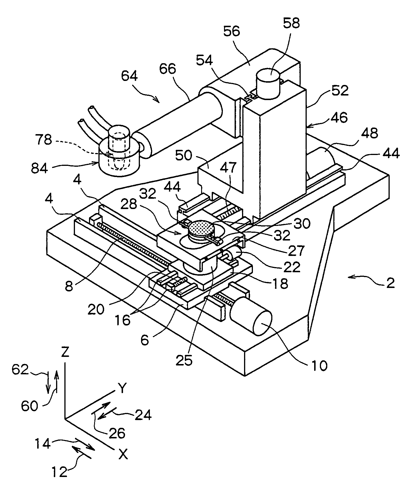
[0018]FIG. 1 shows a principal portion of a preferred embodiment of the machining device constructed according to the present invention. The illustrated machining device has a support plate 2, and a pair of guide rails 4 extending in an X-axis direction are disposed on the support plate 2. A first slide block 6 is mounted on the guide rails 4 so as to be movable in the X-axis direction. A threaded shaft 8 extending in the X-axis direction is rotatably mounted between the pair of guide rails 4, and an output shaft of a pulse motor 10 is connected to the threaded shaft 8. The first slide block 6 has a downward portion (not shown) extending downwardly, and an internally threaded hole piercing in the X-axis direction is formed in the downward portion. The threade...


PUM

PropertyMeasurementUnit
dielectric constantaaaaaaaaaa
wavelengthaaaaaaaaaa

Abstract

A machining device comprises workpiece holding means for holding a workpiece, laser beam machining means for shining a laser beam to the workpiece held by the workpiece holding means to machine the workpiece, and moving means for moving the workpiece held by the workpiece holding means, and a laser beam shone to the workpiece relative to each other. Suction means is disposed for sucking from a machining region where the laser beam is shone to the workpiece. The suction means includes a central hood, a central suction source for sucking through the central hood, an outer hood, and an outer suction source for sucking through the outer hood, and the suction force of the central suction source is greater than the suction force of the outer suction source.

Description

TECHNICAL FIELD[0001]This invention relates to a machining device for shining a laser beam to a workpiece to machine the workpiece. More specifically, the invention relates to, but is not limited to, a machining device suitable for removing a low dielectric constant insulator, laminated on the face of a semiconductor wafer, along predetermined lines.BACKGROUND ART[0002]In the manufacture of semiconductor chips, as is well known among people skilled in the art, a plurality of rectangular regions are defined on the face of a semiconductor wafer by streets arranged in a lattice pattern, and a semiconductor circuit is formed in each of the rectangular regions. This semiconductor wafer is cut along the streets to separate the rectangular regions individually, thereby forming semiconductor chips. For cutting along the streets, a machining device called a dicer is usually used. Such a machining device comprises workpiece holding means for holding a workpiece, namely, a semiconductor wafer,...

Claims


Application Information

Patent Timeline
Patent Type & Authority Patents(United States)
IPC IPC(8): B23K26/00B08B15/04B23K26/14B23Q11/00H01L21/301
CPCB08B15/04B23K26/0853B23K26/123B23K26/14B23Q11/0046B23K26/1476B23K26/38B23K26/4075B23K26/1405B23K2201/40B23K26/40B23K26/142B23K2101/40B23K2103/50B23K26/16
Inventor SEKIYA, KAZUMA
Owner DISCO CORP
Why Eureka
Try Eureka