Four color image sensing apparatus
a color image and sensing technology, applied in the field of color imaging apparatus, can solve the problems of inability to provide simultaneous rgb color content, inability to produce black, inability to produce cyan, magenta and yellow, etc., and achieve the range of colors that can be represented by printing pigments
- Summary
- Abstract
- Description
- Claims
- Application Information
AI Technical Summary
Benefits of technology
Problems solved by technology
Method used
Image
Examples
second embodiment
[0039]A second embodiment is shown in FIG. 3, wherein a single camera 20 with a single area array photosensor 30 is used with a color filter wheel 25 containing red 10R, green 10G, blue-green 10BG, and blue 10B filters positioned in front of the camera and a color sequential signal produced. Color filter wheel 25 can be replaced by an electronically switchable LCD color filter such as devices made by ColorLink Inc., Boulder, Colo. This type of color filter is typically operated between crossed polarizers (not shown).
[0040]Referring again to FIG. 3, camera 20 comprises an image acquisition unit 120 that contains the optical and electronic components for focus, sensing, and initial light acquisition. A signal processing unit 126 accepts and processes the sensed data values from photosensor 30. For the apparatus shown in FIG. 3, signal processing unit 126 processes the sequential color data that is output from imaging acquisition unit 120. A control logic processor 122, typically a mic...
third embodiment
[0041]A third embodiment is shown in FIG. 4, wherein camera 20 has four area array photosensors 30, and white light 16 from a scene is spectrally divided for the four sensors 30R, 30G, 30BG, 30B, one each for red, green, blue-green, and blue. White light 16 passes through lens 15, and is divided by a dichroic mirror 32 into red light and blue-green light. The red light, in this case, reflects from dichroic mirror 32 and impinges onto CCD array 30R. The blue, green, and blue-green light is transmitted to a beamsplitter 36, which could be a pellicle or partially silvered mirror, for example. Beamsplitter 36 does not have to divide the light equally. For example, two-thirds of the light could be directed to the blue sensor and the green sensor and one-third of the light could be directed to the blue-green sensor. Blue and green light are reflected from beamsplitter 36 and directed toward a dichroic mirror 34. Blue-green light is transmitted through beamsplitter 36 and goes to blue-gree...
fourth embodiment
[0042]A fourth embodiment is shown in FIG. 5, wherein an X-cube 38 is used to separate the s-polarized red and blue colors (denoted by the dots) from the incoming light from lens 15. A filter 32 reflects red, blocking red light that may leak through X-cube 38 and passes blue and green. A dichroic mirror 34 is used to complete and clean up the color separation. The x-cube passes green of both polarizations (as shown by the dot and the arrow) and will also pass s-polarized (arrow) blue and red light. Dichroic filter 34 is designed to reflect the remainder of the blue and the shorter wavelengths of the green light to blue-green sensor 30BG. The balance of the green light is transmitted to green sensor 30G.
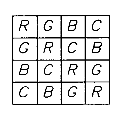
[0043]FIG. 6 shows a preferred arrangement of RGBC filters in a color filter array. In one embodiment, fourth color C is cyan, the blue-green filter that can have a narrower bandwidth than the full blue and green spectra, which ranges from the 400 to 600 nm normally be associated with...
PUM
 Abstract
Description
Claims
Application Information
 - R&D
- Intellectual Property
- Life Sciences
- Materials
- Tech Scout
- Unparalleled Data Quality
- Higher Quality Content
- 60% Fewer Hallucinations
Browse by: Latest US Patents, China's latest patents, Technical Efficacy Thesaurus, Application Domain, Technology Topic, Popular Technical Reports.
© 2025 PatSnap. All rights reserved.Legal|Privacy policy|Modern Slavery Act Transparency Statement|Sitemap|About US| Contact US: help@patsnap.com


