
Compact multipass optical isolator

a multi-pass, compact technology, applied in non-linear optics, instruments, optics, etc., can solve the problems of large optical absorption loss, inability to use, and increased cost, and achieve the effect of increasing the effective interaction length

Inactive Publication Date: 2006-06-06
AHURA CORP
View PDF1 Cites 13 Cited by
  • Summary
  • Abstract
  • Description
  • Claims
  • Application Information

AI Technical Summary

Benefits of technology

"The present invention provides an optical isolator that uses a volume of crystal several times by reflecting light inside the crystal multiple times. This increases the effective interaction length by the number of bounces within the crystal. The isolator is compact, low cost, and manufacturable. It can be implemented at any desired wavelength and is insensitive to magnetic field distortion. The isolator uses a Faraday rotator material with a given Verdet constant, a first end, and a second end. The optical pathway through the Faraday rotator material is longer than the maximum linear distance between the first and second ends. The isolator also includes an input polarizer and an output polarizer, a Faraday rotator material with a given magnetic field applied thereto, and at least one reflector. The method of optically isolating light involves transmitting light in one direction and blocking it in another direction, and the optical pathway through the Faraday rotator material is longer than the length of the crystal."

Problems solved by technology

A major draw back for BIG materials is that their window of optical transparency is limited to above 1100 nm wavelength range and in visible and Near-IR wavelength (less than 1000 nm) BIG has large optical absorption loss and is not usable.
However, magneto-optic crystals suffer from three fundamental problems.
Such multistage isolators add to the cost and make the size of the isolator almost impractical for most applications.

Method used


Image

  • Compact multipass optical isolator
  • Compact multipass optical isolator
  • Compact multipass optical isolator

Examples


Embodiment Construction

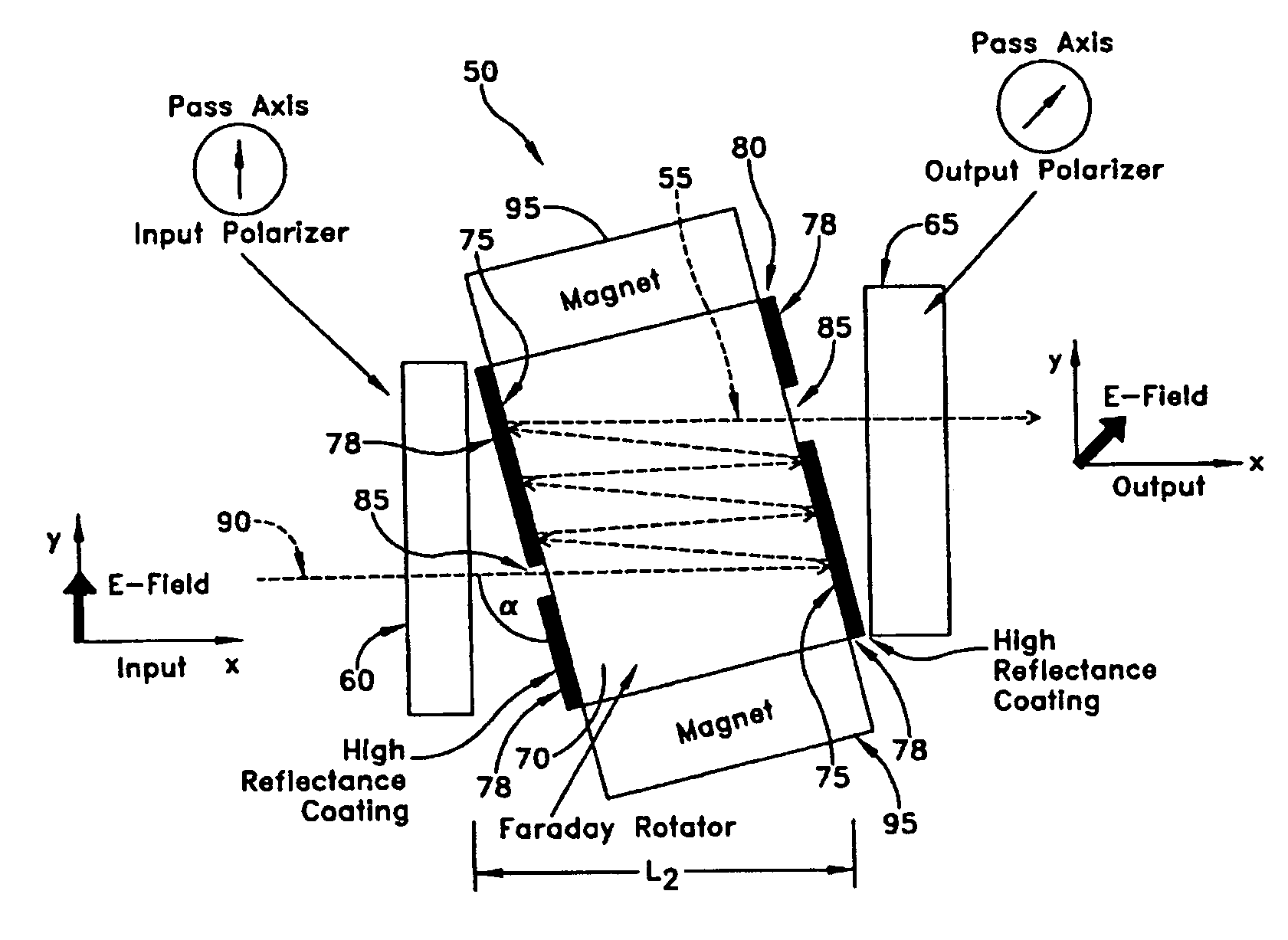
[0044]Referring to FIG. 3, and in a preferred embodiment of the present invention, there is shown a novel multipass optical isolator 50, which uses multiple optical passes 55 to reduce the physical size while maintaining the needed optical path length from input polarizer 60 to output polarizer 65.

[0045]Faraday rotator material 70 of optical isolator 50 has a pair of opposing facets 75 which are covered with a high reflecting coating 78 so as to form a multipass etalon 80. A small uncoated region 85 is patterned on each facet 75 to allow light 90 to enter and exit etalon 80.

[0046]Referring still to FIG. 3, and in a preferred embodiment of the present invention, the angle of incidence α of light 90 to Faraday rotator etalon 80 is selected to set the desired number of reflections off of high reflecting coating 75 which in turn allows the desired number of passes through Faraday rotator material 70. One or more magnets 95 are configured adjacent to Faraday rotator material 70 so as to ...


PUM

PropertyMeasurementUnit
angleaaaaaaaaaa
wavelengthaaaaaaaaaa

Abstract

An optical isolator is disclosed for transmitting light in a first direction and blocking light in a second direction along an optical pathway. The optical isolator includes an input polarizer having a pass axis at first angle, an output polarizer having a pass axis at second angle, a Faraday rotator material between the polarizers having a Verdet constant and an axis of maximum length therethrough, generation means for generating a magnetic field around and inside the rotator material, and at least one reflector configured to define an optical length through the rotator material which is longer than the axis therethrough. The optical pathway length through the rotator material, the magnetic field strength, and the Verdet constant are selected so as to rotate light through the Faraday rotator material from the first angle to the second angle.

Description

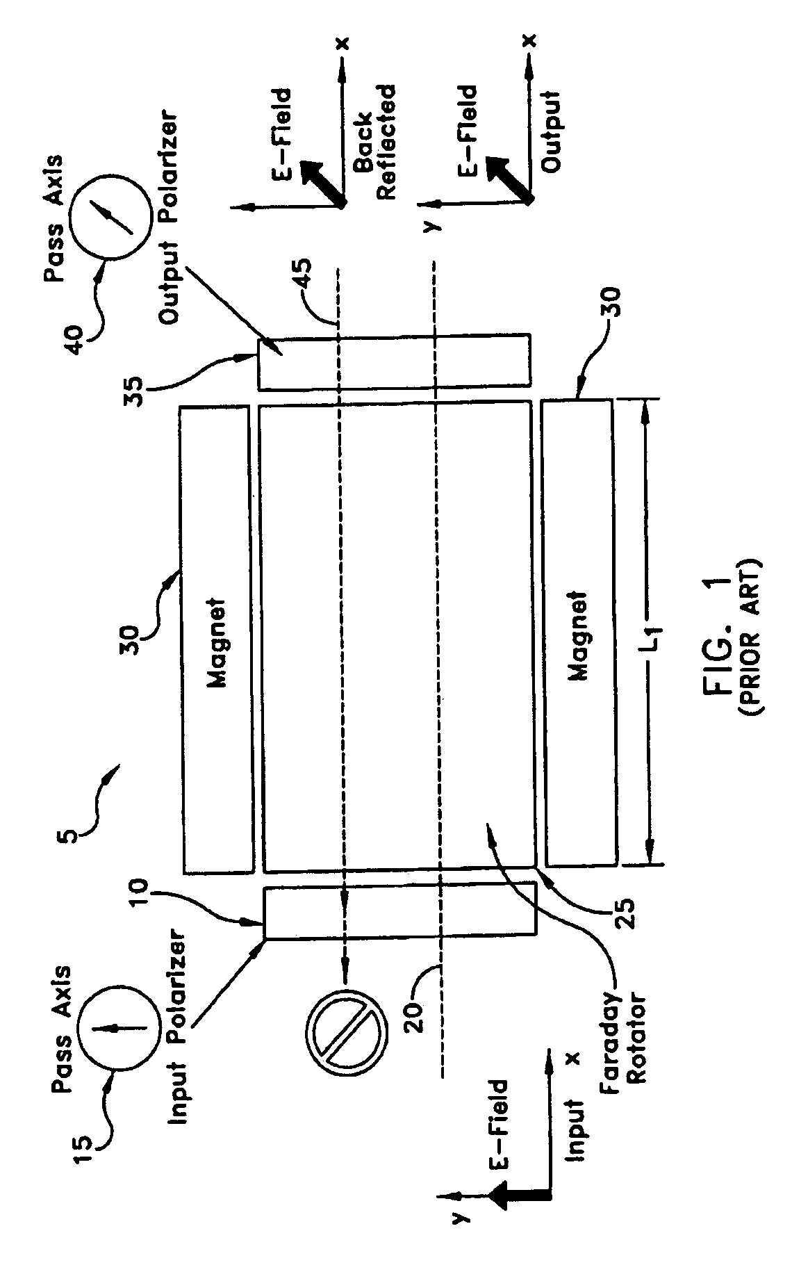
REFERENCE TO PENDING PRIOR PATENT APPLICATION[0001]This patent application claims benefit of pending prior U.S. Provisional Patent Application Ser. No. 60 / 454,223, filed Mar. 13, 2003 by Kevin Knopp et al. for COMPACT MULTIPASS OPTICAL ISOLATOR, which patent application is hereby incorporated herein by reference.FIELD OF THE INVENTION[0002]This invention is related to free space optics and fiber optic applications apparatus and methods in general, and more particularly to apparatus and methods for optical isolation of light.BACKGROUND OF THE INVENTION[0003]Optical isolators are key elements required in most free space optic and fiber optic applications. The most commonly used type of isolator is based around a Faraday rotator crystal. FIG. 1 is a schematic diagram that illustrates a typical configuration of a conventional optical isolator 5. An input polarizer 10 of isolator 5 is typically aligned to a linear polarization angle 15 of input light 20. A crystal 25 of a given length L1...

Claims


Application Information

Patent Timeline
Patent Type & Authority Patents(United States)
IPC IPC(8): G02F1/09
CPCG02F1/093G02F2201/17
Inventor AZIMI, MASUDVAKHSHOORI, DARYOOSHKNOPP, KEVIN J.RHODES, GREGORY VANDERWANG, PEIDONG
Owner AHURA CORP
Learn More