Imaging systems, program used for controlling image data in same system, method for correcting distortion of captured image in same system, and recording medium storing procedures for same method

Inactive Publication Date: 2006-06-06
SHARP KK
View PDF19 Cites 15 Cited by
  • Summary
  • Abstract
  • Description
  • Claims
  • Application Information

AI Technical Summary

Benefits of technology

[0015]In one embodiment of the invention, the correction section includes: an image processing section for transforming the captured image data into the perspective transformed image data so as to produce a perspective transformed image; and an operation panel for inputting an instruction to increase or decrease the value regarding the distance between the lens position and the light-receiving surface of the imaging device.
[0044]Thus, the invention described herein makes possible the advantages of providing: an imaging system in which a lens position for producing a central projection image is not limited to one point and the central projection image is produced under a condition where a lens is focused onto an entire surface of a hyperboloidal mirror; software used for controlling data representing the produced image; a method for correcting distortion in an image captured by the imaging system; and a recording medium storing procedures for such a method.

Problems solved by technology

However, in the conventional imaging system using the hyperboloidal mirror, the lens position for producing the central projection image is limited to one point (focus O2).
Thus, it is difficult to align a lens with a position which is optimum for installing the lens.
Moreover, in this lens position (focus O2), in view of performance of the lens, it is not easy to focus the lens on an entire surface of the hyperboloidal mirror for the purpose of capturing an image reflected in the hyperboloidal mirror, since a minimum distance from the lens to a virtual image (an object reflected in the hyperboloidal mirror) formed in the hyperboloidal mirror (a distance between a vertex of the hyperboloidal mirror and the lens) is short.

Method used


Image

  • Imaging systems, program used for controlling image data in same system, method for correcting distortion of captured image in same system, and recording medium storing procedures for same method
  • Imaging systems, program used for controlling image data in same system, method for correcting distortion of captured image in same system, and recording medium storing procedures for same method
  • Imaging systems, program used for controlling image data in same system, method for correcting distortion of captured image in same system, and recording medium storing procedures for same method

Examples


Embodiment Construction

[0064]Hereinafter, examples of the present invention will be described with reference to the drawings.

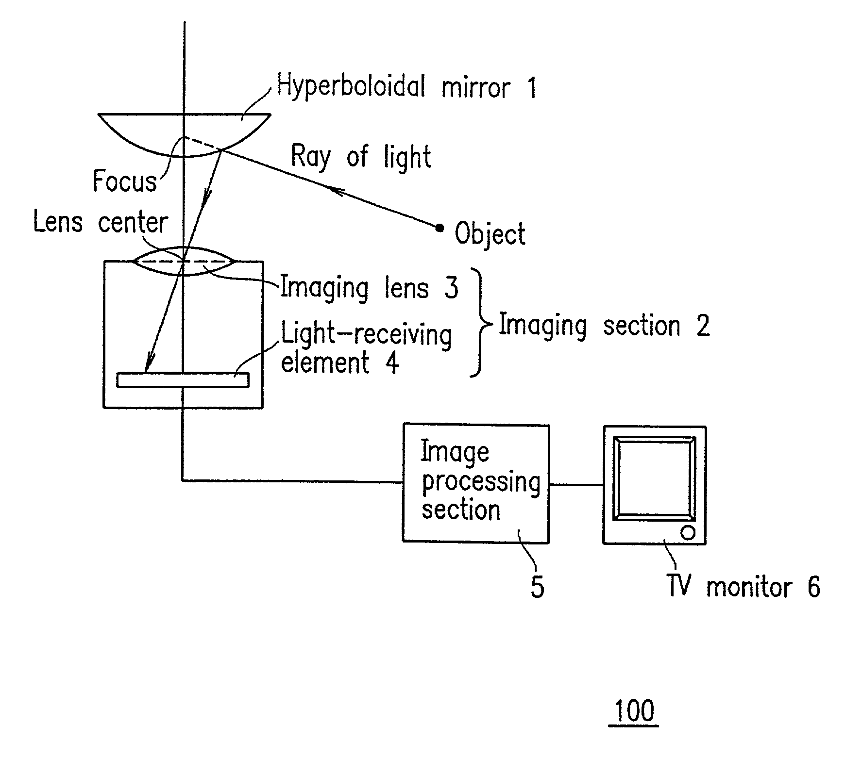
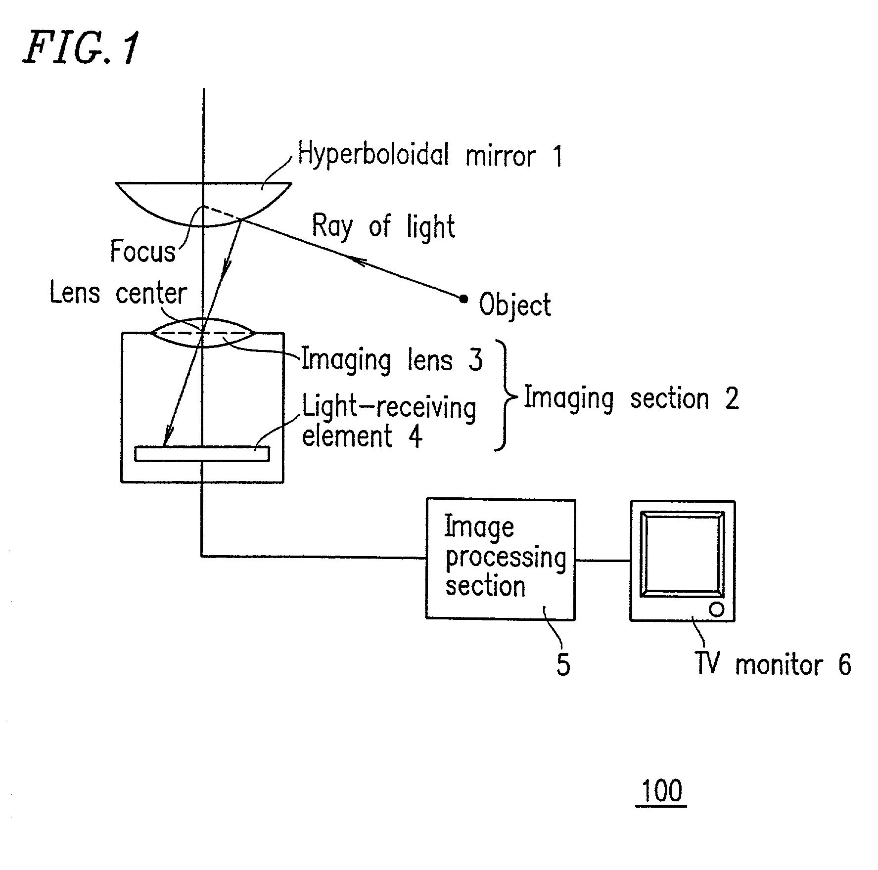
[0065]FIG. 1 is a diagram for explaining a basic structure and geometric positional relationship among components of an imaging system 100 according to an example of the present invention.

[0066]The imaging system 100 includes a hyperboloidal mirror 1, an imaging section 2 (including an imaging lens 3 and a light-receiving element 4), an image processing section 5, and a TV monitor 6.

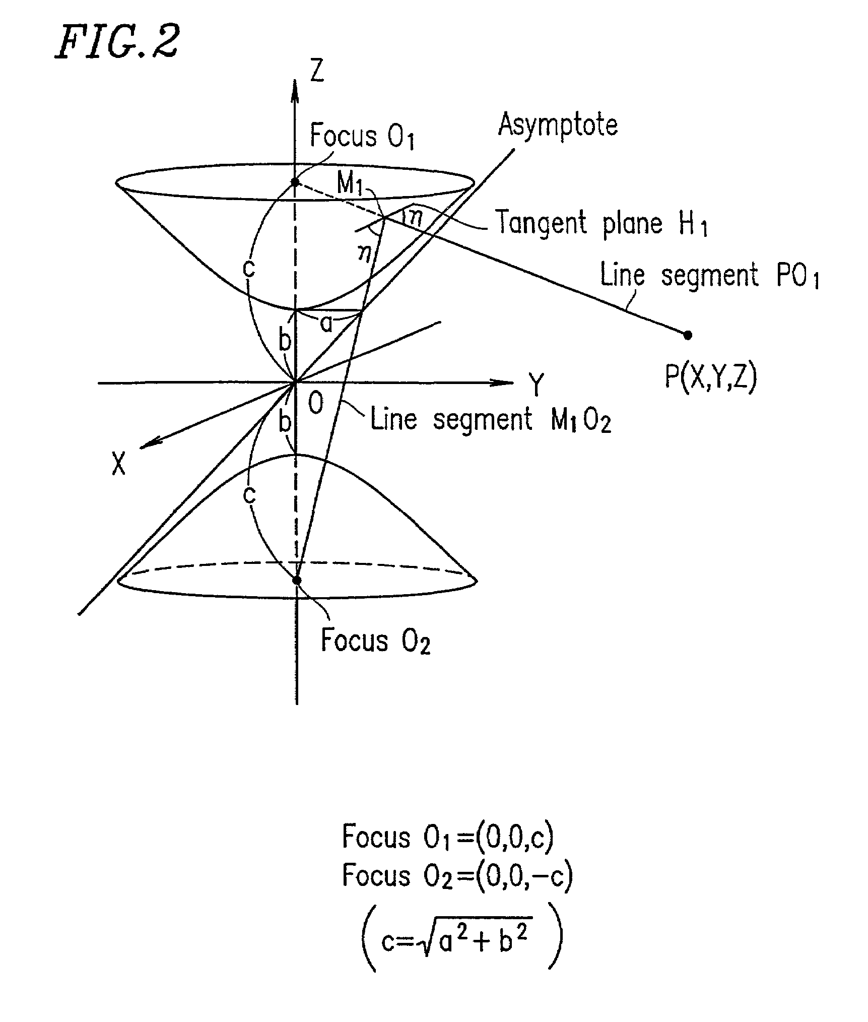
[0067]The hyperboloidal mirror 1 is a reflecting mirror having a geometry of the first sheet of a two-sheeted hyperboloid. A general expression of a two-sheeted hyperboloidal function is represented by the following

[0068]Expression (3):

(X2+Y2) / a2−z2 / b2=−1  (3).

[0069]FIG. 2 illustrates a two-sheeted hyperboloid when graphically representing Expression (3).

[0070]The two-sheeted hyperboloid illustrated in FIG. 2 has a rotation axis along the Z-axis, focus O1 on the Z-axis in a positive direction, and focus ...


PUM


Abstract

An imaging system of the present invention includes: a reflecting mirror having a geometry of one of two sheets of a two-sheeted hyperboloid; and an imaging section which includes an imaging device for receiving light concentrated by a lens having a center located in any position opposing the reflecting mirror on a rotation axis of the reflecting mirror, wherein the imaging system includes a correction section for performing coordinate transformation on captured image data obtained by capturing an image of a prescribed inspection drawing so as to produce a perspective transformed image data and for correcting distortion in the captured image based on a value regarding a distance between a lens position adapted for the coordinate transformation and a light-receiving surface of the imaging device.

Description

BACKGROUND OF THE INVENTION[0001]1. Field of the Invention[0002]The present invention relates to: an imaging system capable of capturing a 360-degree field of view image in a single shooting; software used for controlling data representing the captured image; a method for correcting distortion in an image captured by the imaging system; and a recording medium storing procedures for such a method. From the image captured by the imaging system, space geometry, a configuration of an object, etc., can be correctly perceived. Such an imaging system can be preferably used in wide-ranging fields including the field of security for monitoring stores, banks, etc.; the field of on-vehicle use, such as avoidance of automobile collision, and monitoring of the inside of a vehicle; and the field of measuring instruments for use in a visual section of an industrial robot, for example.[0003]2. Description of the Related Art[0004]In a conventional imaging system capable of capturing a 360-degree fie...

Claims


Application Information

Patent Timeline
IPC IPC(8): G06K9/40G02B17/08G02B27/00G06T3/00G06T5/00H04N5/225H04N5/262
CPCG02B27/0025G06T5/006H04N5/2628H04N5/23238H04N5/2254H04N23/698G06T5/80H04N23/00
Inventor WAKAMOTO, SETSUNOBUKUMATA, KIYOSHISHIGETA, TOHRUKAWAKAMI, KENICHINAKANO, KOHICHI
Owner SHARP KK
Why Eureka
Try Eureka