Eureka AIR delivers breakthrough ideas for toughest innovation challenges, trusted by R&D personnel around the world.

Method and apparatus for detecting maximum and minimum values, and torque detecting apparatus and steering apparatus comprising the maximum and minimum values detecting apparatus

Inactive Publication Date: 2006-06-06
KOYO SEIKO CO LTD
View PDF15 Cites 2 Cited by
  • Summary
  • Abstract
  • Description
  • Claims
  • Application Information

AI Technical Summary

Benefits of technology

[0032]As shown in FIG. 4, for example, the signals A and B (a first signal and a second signal) pass a maximum value of the signal A and a minimum value of the signal B, or a minimum value of the signal A and a maximum value of the signal B, within the time interval Tc between a series of two detected crossings. Maximum and minimum values of the signals A and B can be detected based on the maximum and minimum values of the signals A and B detected within the time interval Tc. Since passing of the maximum and minimum values are detected based on the crossings of the signals A and B, it is unnecessary to set a particular value such as a threshold. Moreover, there is no problem such that the signals do not exceed a threshold thereby disenabling correction, and correction can be performed reliably.
[0040]As shown in FIG. 4, for example, the signals A and B (a first signal and a second signal) pass a maximum value of the signal A and a minimum value of the signal B, or a minimum value of the signal A and a maximum value of the signal B, within the time interval Tc between a series of two detected crossings. Maximum and minimum values of the signals A and B can be detected based on the maximum and minimum values of the signals A and B detected within the time interval Tc. Since passing of the maximum and minimum values can be detected based on the crossings of the signals A and B which are detected by the crossing detecting means, it is unnecessary to set a particular value such as a threshold. Moreover, there is no problem such that the signals do not exceed a threshold thereby disenabling correction, and correction can be performed reliably.
[0050]Such a steering apparatus detects a torque with high accuracy with the torque detecting apparatus comprising the maximum and minimum values detecting apparatus. Based on the accurately detected torque, the steering assist electric motor can be controlled reliably.

Problems solved by technology

When the detection signals include an error, a torque cannot be calculated accurately.
The above method demands much labor and high costs for making the translation table.
It is hard to detect maximum and minimum values when a period is not constant.
Moreover, it is impossible to detect passing of a maximum value or a minimum value when the detection signals A and B do not come to the upper bound threshold or the lower bound threshold.

Method used


Image

  • Method and apparatus for detecting maximum and minimum values, and torque detecting apparatus and steering apparatus comprising the maximum and minimum values detecting apparatus
  • Method and apparatus for detecting maximum and minimum values, and torque detecting apparatus and steering apparatus comprising the maximum and minimum values detecting apparatus
  • Method and apparatus for detecting maximum and minimum values, and torque detecting apparatus and steering apparatus comprising the maximum and minimum values detecting apparatus

Examples


first embodiment

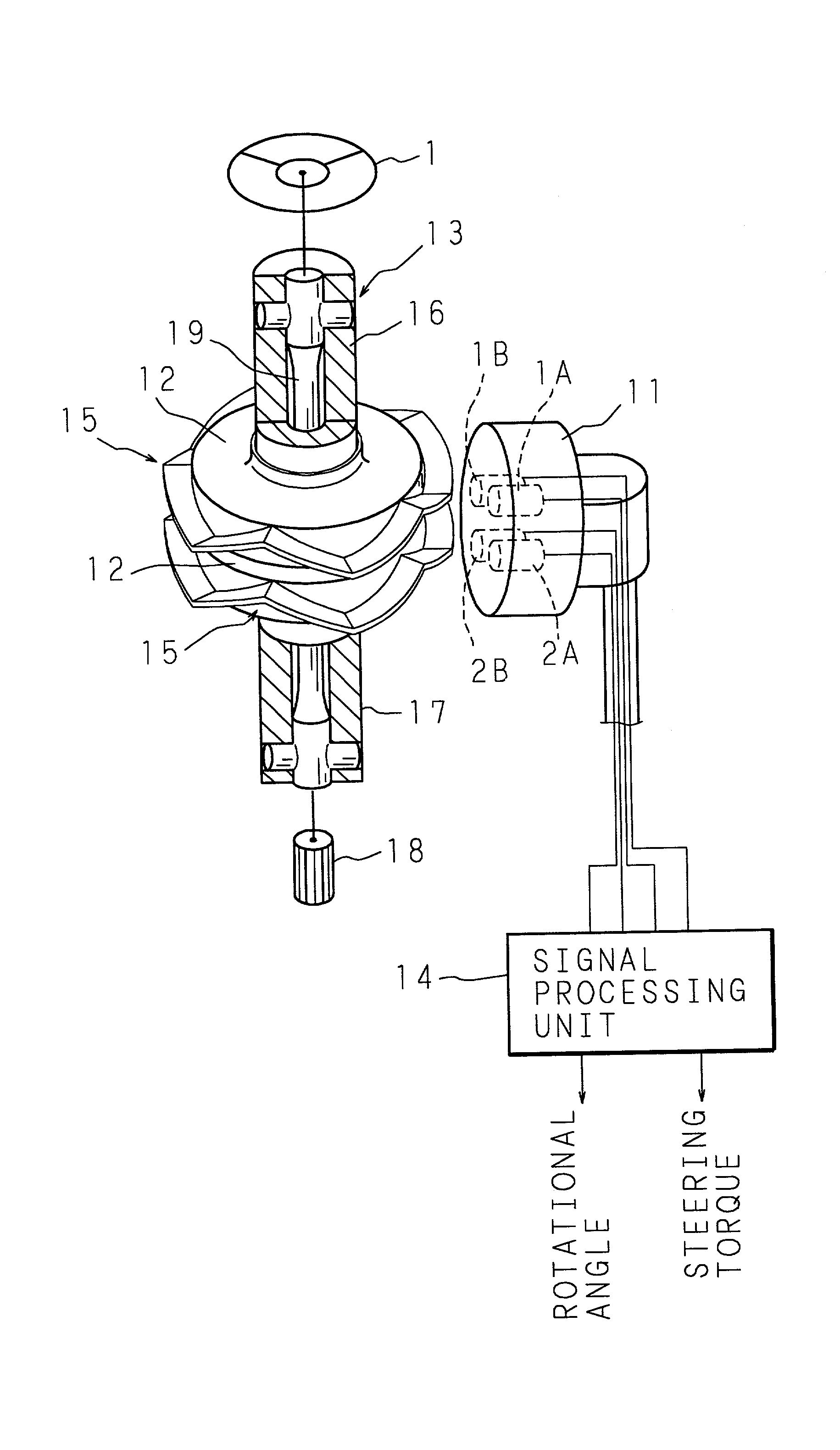
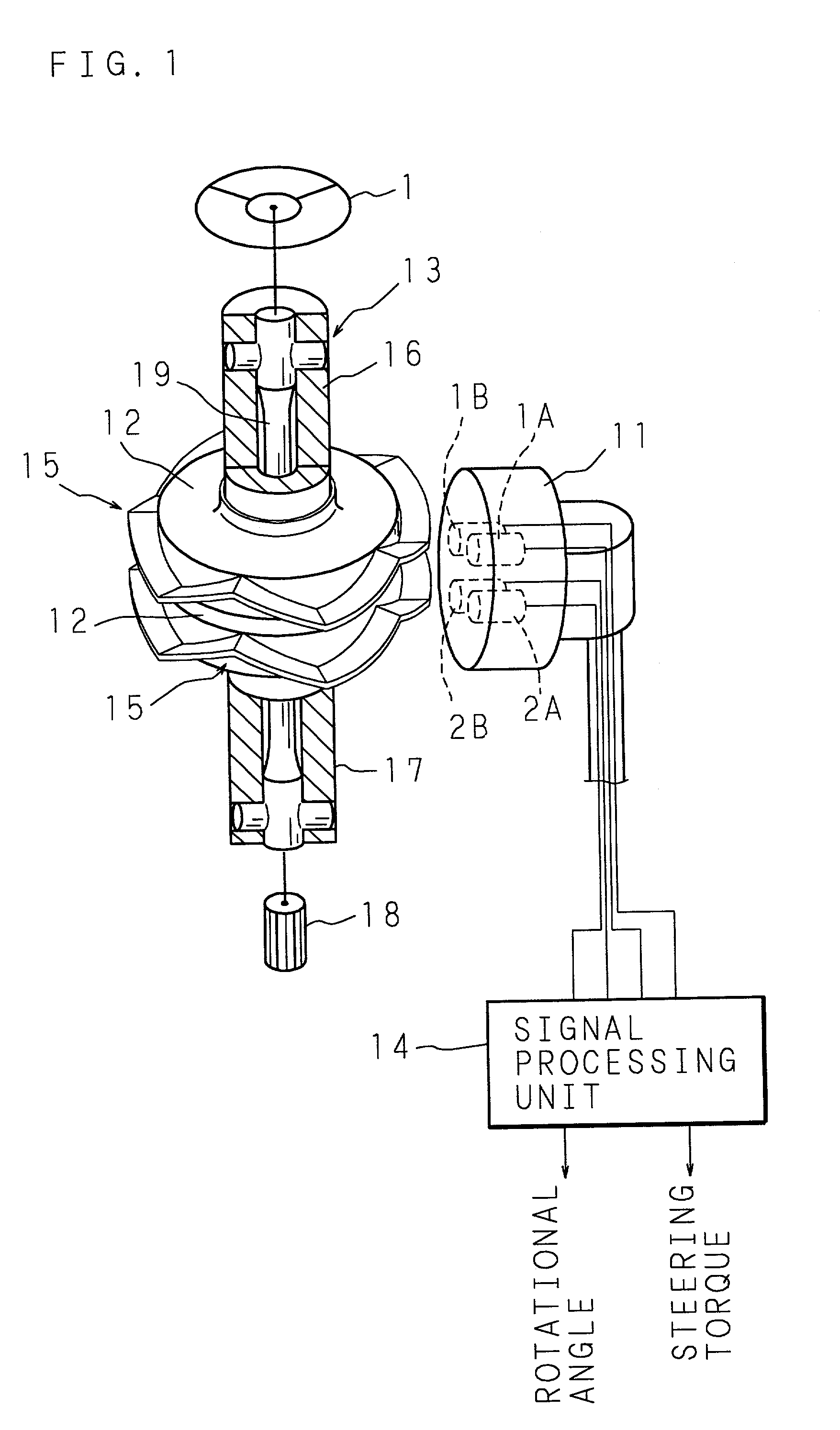
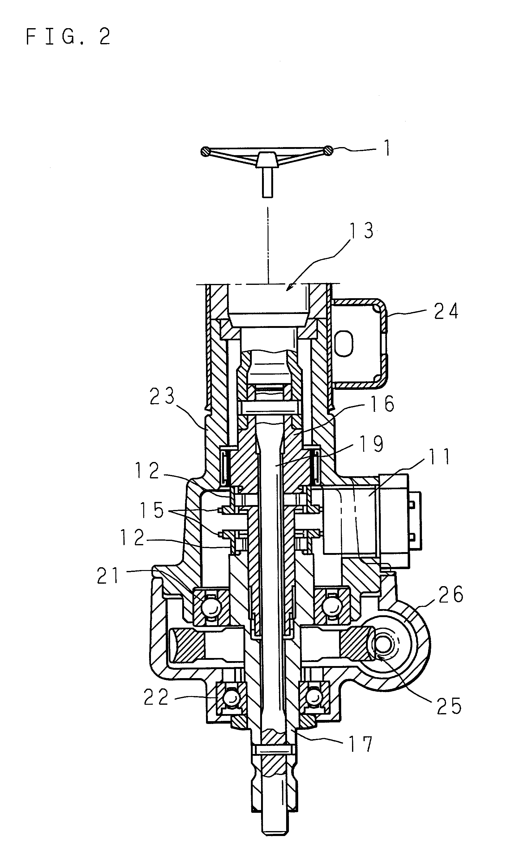
[0064]FIG. 6 shows an example of a constitution of a torque detecting apparatus and a steering apparatus comprising a maximum and minimum values detecting apparatus according to the present invention. Like codes are used to refer to the same parts as those in the conventional apparatus (FIG. 1). The following description will explain correction of detection signals A and B which are, for example, triangular pulses with phases 90° different from each other as shown in FIG. 4. The difference between the phases of the signals A and B is not limited to 90°. Moreover, the signal shape is not limited to a triangular pulse.

[0065]The maximum and minimum values detecting apparatus according to a present invention is included in a signal processing unit 20. The signal processing unit 20 comprises a microprocessor. The signal processing unit 20 operates as: crossing detecting means for detecting a crossing of the detection signals A and B; means for detecting maximum and minimum values (herein...

second embodiment

[0083]FIG. 9 shows another example of a constitution of a torque detecting apparatus and a steering apparatus comprising a maximum and minimum values detecting apparatus according to the present invention. Like codes are used to refer to the same parts as those in the conventional apparatus. The following description will explain correction of detection signals A and B which are, for example, triangular pulses with phases 90° different from each other as shown in FIG. 4.

[0084]The maximum and minimum values detecting apparatus according to the present invention is included in the signal processing unit 20. The signal processing unit 20 comprises a microprocessor. The signal processing unit 20 operates as: crossing detecting means for detecting a crossing of the detection signals A and B; means for detecting maximum and minimum values (hereinafter referred to as “tentative maximum values” and “tentative minimum values”) of the signals A and B within a time interval Tc between a series...


PUM


Abstract

The method and apparatus for detecting maximum and minimum values, and the torque detecting apparatus and steering apparatus comprising the maximum and minimum values detecting apparatus can detect maximum and minimum values of detection signals without setting a particular value such as a threshold. A signal processing unit provided at the maximum and minimum values detecting apparatus detects a crossing of two detection signals outputted from two MR sensors, and detects maximum and minimum values of the signals based on maximum and minimum values of the signals detected within a time interval defined by the time when a crossing is detected.

Description

[0001]This application claims foreign priority benefit of Japanese Patent Application 2001-126679 filed on Apr. 24, 2001, the disclosure of which is hereby incorporated by reference.BACKGROUND OF THE INVENTION[0002]1. Field of the Invention[0003]The present invention relates to a method and an apparatus for detecting maximum and minimum values of two detection signals with different phases which are outputted from a rotational angle detecting device provided in a torque detecting apparatus and a steering apparatus, and a torque detecting apparatus and a steering apparatus comprising the maximum and minimum values detecting apparatus.[0004]2. Description of Related Art[0005]Some steering apparatuses for vehicles assist steering by driving an electric motor so as to reduce driver's load. Such a steering apparatus comprises: an input shaft joined to a steering wheel; an output shaft joined to tire wheels via a pinion and a rack, for example; a connecting shaft for connecting the input ...

Claims


Application Information

Patent Timeline
IPC IPC(8): G01L1/00G01L3/00G01L5/00G06F19/00B62D5/04B62D5/06B62D6/10G01B7/00G01B7/30G01D5/18G01D5/244G01D5/245G01L3/10G01L5/22
CPCB62D6/10G01L5/221G01L3/101G01L3/104
Inventor MAEDA, NAOKI
Owner KOYO SEIKO CO LTD
Why Eureka
Eureka Blog
Learn More