Tracheostoma valve

a tracheostoma valve and valve body technology, applied in the field of tracheostoma valves, can solve the problems of not always practical or pleasant, no single closure can have the correct mechanical characteristics, complex multi-component mechanism of devices, etc., and achieve the effect of facilitating speech

Inactive Publication Date: 2006-06-13
KAPITEX HEALTHCARE
View PDF10 Cites 28 Cited by
  • Summary
  • Abstract
  • Description
  • Claims
  • Application Information

AI Technical Summary

Benefits of technology

[0013]It is an object of the present invention to provide a tracheostoma valve which facilitates speech in laryngectomy patients by remaining open under the pressure of normal vegetative breathing but closing under the pressure associated with speech.

Problems solved by technology

However, this is not always practical or pleasant, particularly given that the stoma often is coated by secretion and can have an irregular shape.
In such a device valve closure pressures are such that normal vegetative breathing pressure is insufficient to move the closure to a closed position and the patient may readily inhale and exhale normally.
First, a further “cough” valve is often provided as a safety feature closed at normal and speaking pressures but whereby very high pressures cause this to open.
Second, with different patients and changing exertion and respiration levels, no single closure can have the correct mechanical characteristics to work ideally in all situations, and some prior art valves are adjustable, for example by means of a screw thread setting distance between open and closed position and / or the exchanging of interchangeable springs biasing the valve to alter the closure pressure, to allow this to be changed by the patient.
These prior art devices all have complex multi-component mechanisms.
This can raise costs, increase the possibility of malfunctions, and in particular make the tracheostoma valves difficult to operate and keep clean.
This last point can be a particular problem.
The valves can easily become contaminated with mucus from the trachea and / or with dust and like contaminants from outside.
This is a particular problem in patients who have had a laryngectomy, since the procedure itself tends to lead to an increase in mucus production.
Not all prior art devices are compatible for use with such prior art stoma filters, such as heat-moisture exchange (HME) filters.

Method used


Image

  • Tracheostoma valve
  • Tracheostoma valve
  • Tracheostoma valve

Examples


Embodiment Construction

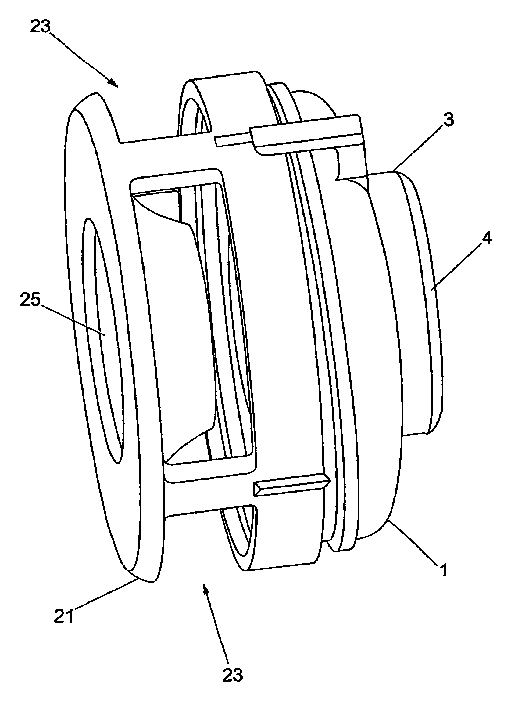
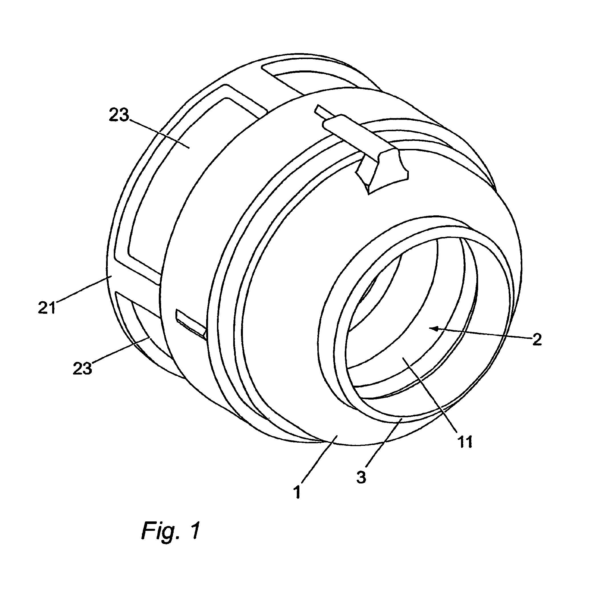
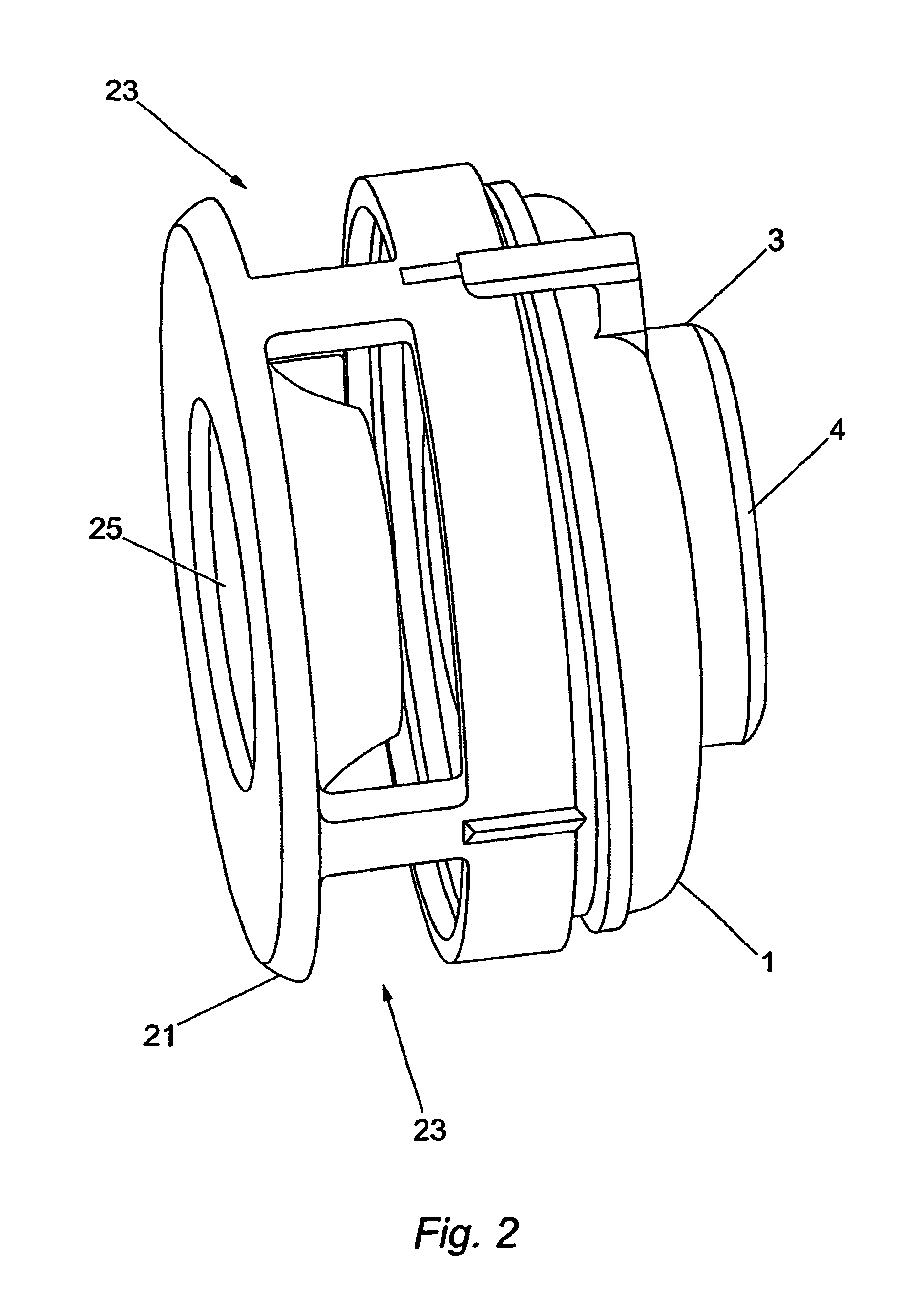
[0020]The invention is characterised in that the valve member comprises a rear portion fixedly mounted to an inner surface of the valve housing rearward of the forward aperture so as to surroundingly and sealingly engage over the rearward aperture, a forward portion, and a collapsibly expandable sleeve portion provided therebetween to surroundingly define a part of the air flow passage, such that the forward portion is deployable from a position in the unexpanded configuration whereat the air flow passage is open to a position in the expanded configuration whereat the forward portion acts to restrict air flow through the air flow passage.

[0021]In use air passes during normal vegetative exhalation first through the rear aperture in the rear wall of the valve housing then into the valve cavity, then out through an aperture or apertures within the forward portion (i.e. the side wall portion or forward wall) of the valve housing. During inhalation the air passage route is reversed. Unde...


PUM


Abstract

A tracheostoma valve is described for use within a tracheostoma to facilitate speech by use of a vocal prosthesis, which consists of a valve housing defining a valve cavity having an airflow passage therethrough between at least one rearward and at least one forward aperture, and a valve member. The valve member includes a fixed rear portion connected to a forward portion by a collapsible sleeve such that the forward portion is deployable from a collapsed configuration under vegetative breathing pressure wherein the air flow passage is open to an expanded configuration under speech pressure whereat the forward portion acts to restrict flow through the air flow passage.

Description

[0001]This is a National Stage of Application No. PCT / GB2003 / 00248, filed Jan. 22, 2003.[0002]The invention relates to a valve to be connected to a tracheostoma to facilitate speech.BACKGROUND OF THE INVENTION[0003]Normal human speech makes use of expired air from the lungs flowing up through the trachea and the larynx to vibrate the vocal cords in the larynx. As a result of disease it is sometimes necessary to remove by surgery a portion of the trachea which may include the larynx (laryngectomy).[0004]Since the larynx normally serves also to prevent contamination of the lungs by oesophageal contents, the passage between the trachea and the pharyngeal oesophagus must be blocked. Consequently at laryngectomy an opening, or stoma, is created to the outside of the throat at the base of the patients neck to which the trachea is permanently diverted. In such patients breathing is then through this tracheostoma.[0005]To restore vocal function it becomes necessary to provide alternative so...

Claims


Application Information

Patent Timeline
Patent Type & Authority Patents(United States)
IPC IPC(8): A61M16/00A61F2/20
CPCA61F2/20A61M16/1045A61M16/0468
Inventor WORTHINGTON, IAN DAVID
Owner KAPITEX HEALTHCARE
Why Eureka
Try Eureka