Knee brace providing dynamic tracking of the patello-femoral joint

a dynamic tracking and knee brace technology, applied in the field of knee braces, can solve the problems of subluxation or dislocation of the joint, subluxation or dislocation of the patella due to patellar tracking errors having the greatest risk of occurring, and high undesirable functional disorders of the patello-femoral joint, so as to increase the tension force, reduce the tension force, and increase the tension force

Inactive Publication Date: 2006-06-13
BREG
View PDF37 Cites 74 Cited by
  • Summary
  • Abstract
  • Description
  • Claims
  • Application Information

AI Technical Summary

Benefits of technology

[0009]When the first upper and lower arms and tension strap lever rotationally transition from the flexion position to the extension position, the tension strap connection point is posteriorly displaced relative to the hinge pivot more distal from the patella, thereby increasing the tension force applied to the compression member. Conversely, when the first upper and lower arms and tension strap lever rotationally transition from the extension position to the flexion position, the tension strap connection point is anteriorly displaced relative to the hinge pivot more proximal to the patella, thereby decreasing the tension force applied to the compression member. The brace is further provided with a counterbalance connector connected to the tension strap.
[0010]The present brace enables a method for maintaining proper tracking of the patella relative to the femoral head during range of motion movement of the knee joint. The method is initiated by placing the compression member in engagement with the knee joint at a location on the femoral head adjacent to the patella. The compression member is aligned with a desired dynamic patellar track. Range of motion movement is then performed on the knee joint by moving the knee joint from a flexion position to an extension position or from an extension position to a flexion position while applying a tension force to the compression member by the tension strap. The tension force increases when the tension strap connection point is posteriorly displaced away from the patella by the first hinge assembly as the knee joint approaches the extension position. Conversely, the tension force decreases when the tension strap connection is anteriorly displaced toward from the patella by the first hinge assembly as the knee joint approaches the flexion position. As such, the compression member presses against the femoral head with a variable tension force which enables the compression member to conform the patella to the desired dynamic patellar track during movement of the knee joint.

Problems solved by technology

In still more severe forms of patello-femoral joint disorder, patellar tracking errors result in subluxation or dislocation of the joint.
Minor subluxation is often the result of a functional imbalance in the knee joint.
In addition, subluxation or dislocation of the patella due to patellar tracking errors has the greatest risk of occurring when the knee joint is approaching extension.
Functional disorders of the patello-femoral joint are highly undesirable because such disorders may ultimately lead to cartilage damage and arthritis of the knee joint.

Method used


Image

  • Knee brace providing dynamic tracking of the patello-femoral joint
  • Knee brace providing dynamic tracking of the patello-femoral joint
  • Knee brace providing dynamic tracking of the patello-femoral joint

Examples


Embodiment Construction

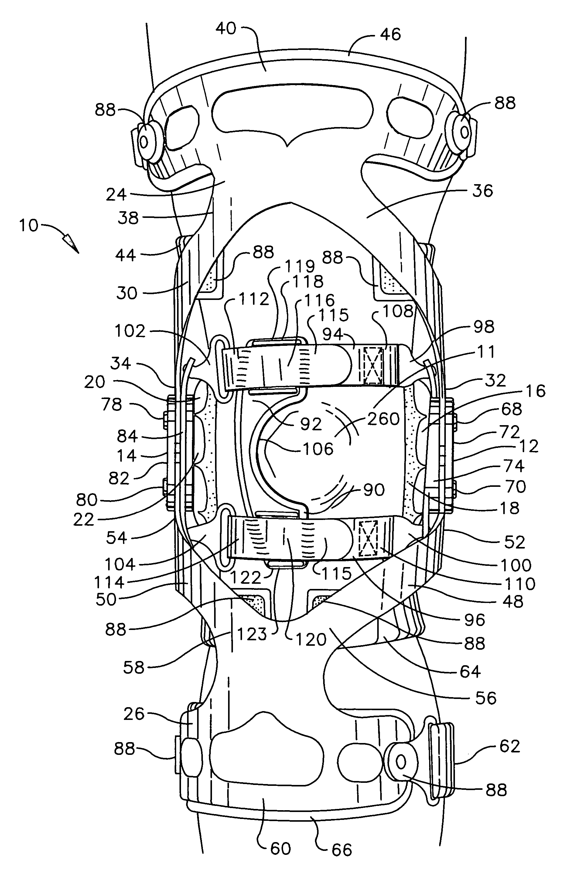
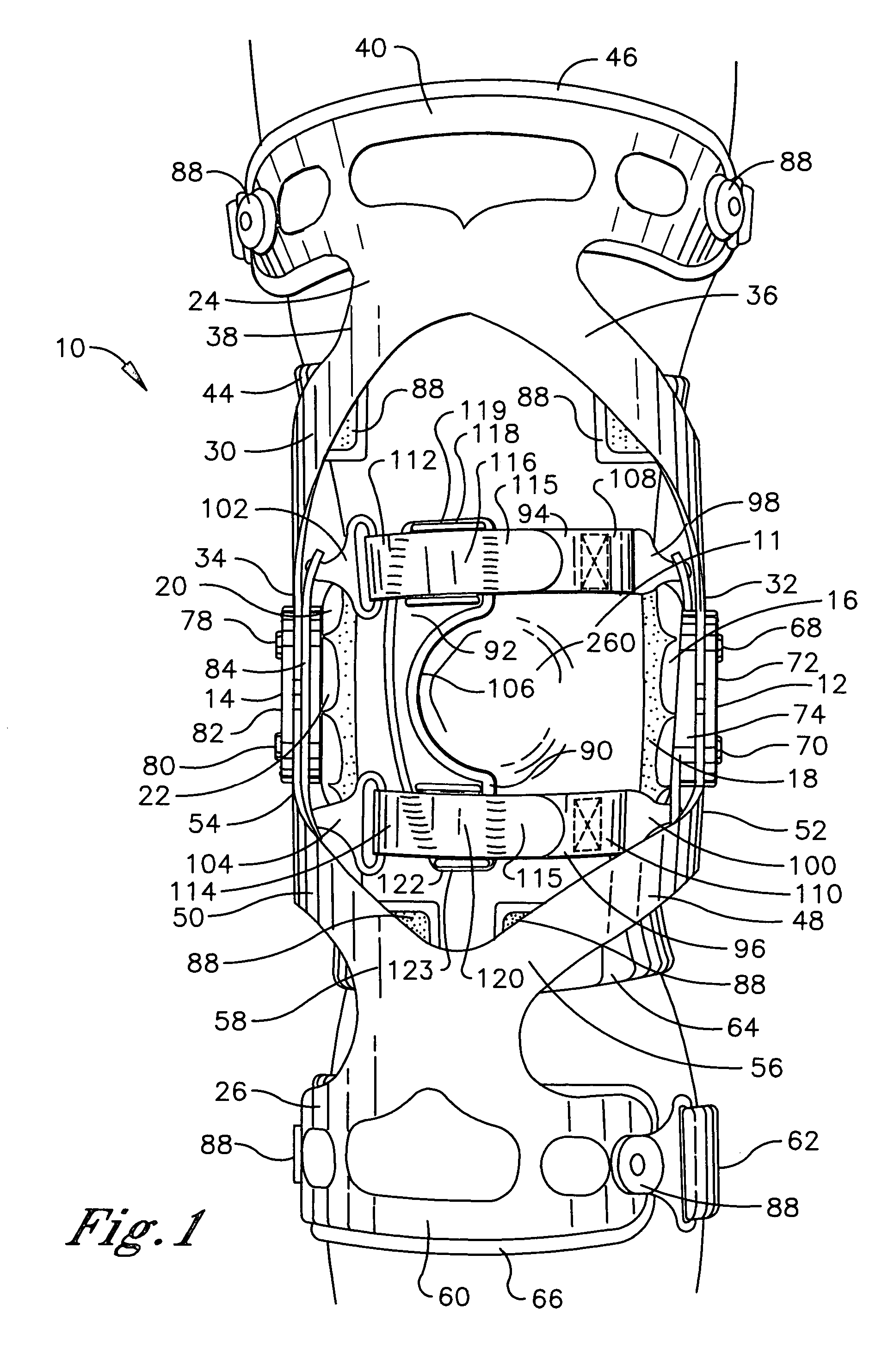
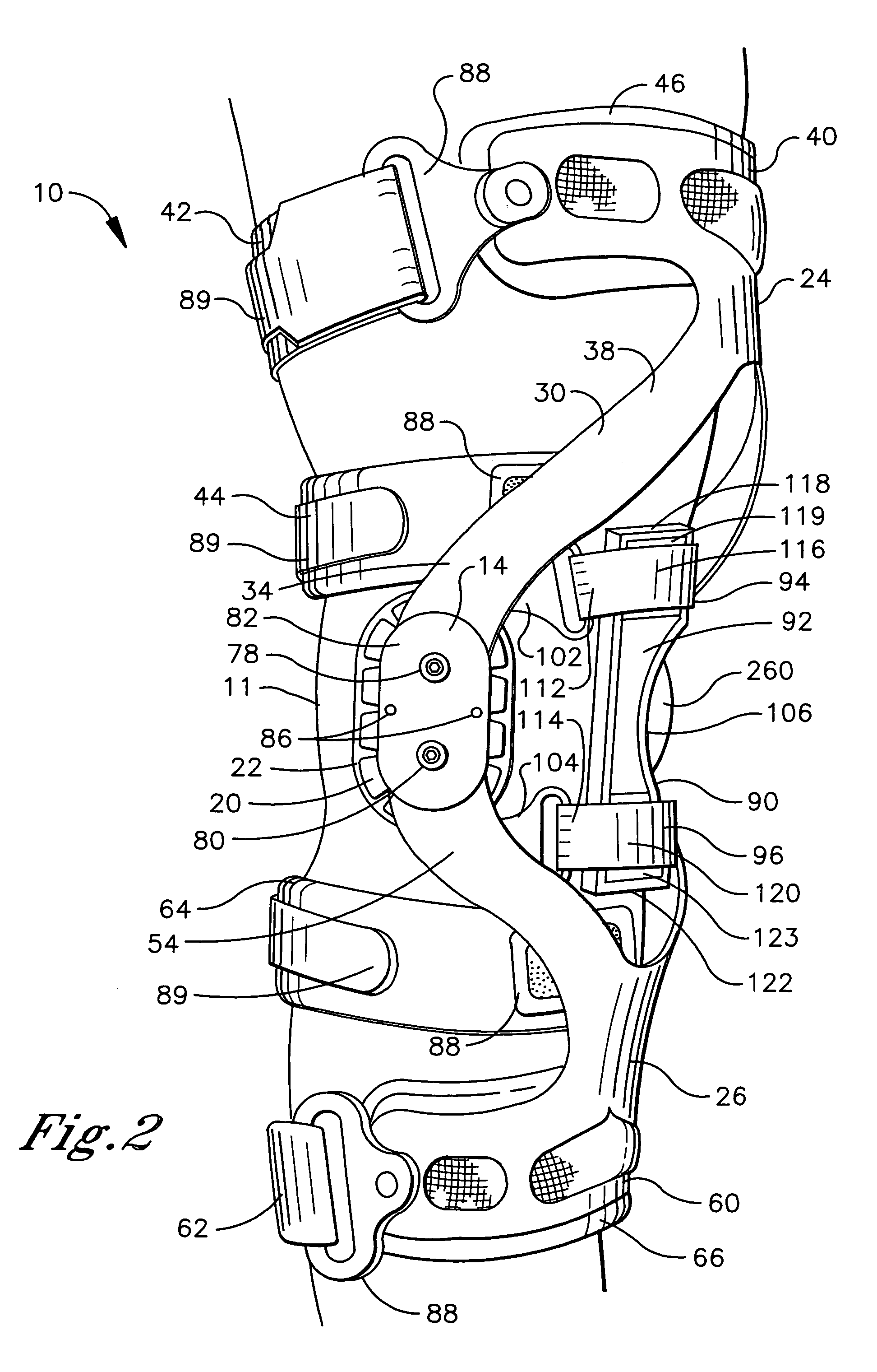
[0020]Referring initially to FIGS. 1–4, a knee brace of the present invention generally designated 10 is shown operatively positioned about the knee joint 11 of a user. For purposes of illustration, the knee brace 10 is configured for mounting on the right leg, but it is understood that the skilled artisan can readily adapt the knee brace 10 for mounting on the opposite leg in accordance with the instant teaching. The positional terms “upper” and “lower” are used hereafter to define the vertical position of an element relative to the knee joint 11. The positional terms “medial” and “lateral” and “anterior” and “posterior” are used hereafter to define the horizontal position of an element relative to the vertical longitudinal axis of the body.

[0021]The knee brace 10 comprises a first hinge assembly 12 and a second hinge assembly 14. A first condyle engagement assembly comprising a first condyle cup 16 and a first condyle pad 18 is associated with the first hinge assembly 12. A second...


PUM


Abstract

A knee brace is provided having upper and lower arms and a hinge assembly positionable about the knee to one side of the patella. The hinge assembly has a hinge pivot and a tension strap lever. The upper and lower arms and tension strap lever are each rotatable about the hinge pivot. A compression member is positioned in engagement with the knee on the opposite side of the patella from the hinge assembly and a tension strap engages the compression member and is connected to the tension strap lever. The tension strap applies a tension force to the compression member which increases when the upper and lower arms and tension strap lever rotationally transition from a flexion position to an extension position and decreases when the upper and lower arms and tension strap lever rotationally transition from the extension position to the flexion position.

Description

[0001]This a continuation-in-part application of Ser. No. 10 / 420,344 filed on Apr. 22, 2003, which is a continuation-in-part application of Ser. No. 09 / 669,061 filed on Sep. 22, 2000 and issued on Apr. 22, 2003, as U.S. Pat. No. 6,551,264.TECHNICAL FIELD[0002]The present invention relates generally to knee braces, and more particularly to a knee brace which causes the patella to properly track the trochlear groove during movement of the knee joint.BACKGROUND OF THE INVENTION[0003]The knee joint includes a patello-femoral joint which is an articulation between the patella and femur. The patello-femoral joint consists of an articular surface on the posterior of the patella and a corresponding articular surface on the anterior of the head of the femur which is termed the trochlea. The posterior of the patella is contoured as a ridge, while the trochlea is contoured as a groove which is dimensioned to receive the patellar ridge in a complementary manner. Proper dynamic function of the p...

Claims


Application Information

Patent Timeline
Patent Type & Authority Patents(United States)
IPC IPC(8): A61C5/14A61F5/01
CPCA61F5/0125A61F2005/0176
Inventor MASON, JEFFREY T.FOUT, JAMES M.VEECK, RAYMOND S.
Owner BREG
Why Eureka
Try Eureka